Board:gigabyte/m57sli: Difference between revisions
No edit summary |
|||
| Line 7: | Line 7: | ||
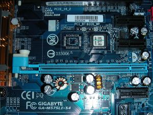
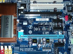
There are 4 volume revisions, 2 with plcc32 (v1.0, v1.1) ([http://www.gigabyte.com.tw/Products/Motherboard/Products_Overview.aspx?ProductID=2287&ModelName=GA-M57SLI-S4 soldered BIOS]) and another 2 with single 8 pin SPI. All 4 have unpopulated secondary pads. For the plcc32 versions, the procedure outlined below can be used to add a rom socket. | There are 4 volume revisions, 2 with plcc32 (v1.0, v1.1) ([http://www.gigabyte.com.tw/Products/Motherboard/Products_Overview.aspx?ProductID=2287&ModelName=GA-M57SLI-S4 soldered BIOS]) and another 2 with single 8 pin SPI. All 4 have unpopulated secondary pads. For the plcc32 versions, the procedure outlined below can be used to add a rom socket. | ||
PLCC32 | |||
{| | |||
| [[Image:m57slis4-plcc32.jpg|thumb|A PLCC32 revision of the M57SLI-S4]] | |||
|} | |||
SPI | SPI | ||
Revision as of 15:00, 30 August 2007
Which board do you have?
The GIGABYTE GA-M57SLI-S4 seems to exist in 4 versions as of 2007/05.
There is a version with a PLCC socket for the BIOS chip (socketed BIOS), but this might be a pre-production board since nobody has so far (2007/03) confirmed the purchase of a GA-M57SLI-S4 board with socketed BIOS.
There are 4 volume revisions, 2 with plcc32 (v1.0, v1.1) (soldered BIOS) and another 2 with single 8 pin SPI. All 4 have unpopulated secondary pads. For the plcc32 versions, the procedure outlined below can be used to add a rom socket.
PLCC32
 |
SPI
 |
Before you begin
The fact that the BIOS is soldered onto the board complicates matters considerably, because it means that one flash of a faulty image will render your board unusable (it will be 'bricked'). Top Hat Flash does not work with the SST 49LF040B 33-4C-NHE soldered onto the M57, but might work with other chips (FWH).
If you have a PLCC revision, it is possible to desolder the BIOS chip, and replace it with a PLCC socket. You will need some tools (heat gun/pencil, good soldering iron, etc) and soldering experience to do that. The other option is to add a PLCC socket to the empty position next to the soldered-on BIOS chip. With an extra resistor and a switch, this allows switching between 2 BIOS chips. This has been documented carefully by ST; see his instructions.
If you don't feel like doing this yourself, you could try to find a commercial service to do it for you. One way to find a shop is to look for game console modification shops, they do this sort of thing (and more advanced things) all day and should be able to help you for around $50 if you bring the needed components (PLCC socket, resistor, wire and switch). Possibly a friendly TV or radio repair shop could help too, but they may not have suitable soldering equipment for the surface mount parts.
If you're going to work on this board, you need a backup plan in the event you flash a faulty BIOS image. You have been warned!
Once you put a socket on the board, you will also discover that the RD1-PMC4 BiosSavior does not work with this motherboard: the RD1's built-in chip seems to be incompatible with the mainboard. This means you will need to hot-swap BIOS chips until you have a working LinuxBIOS chip. Plugging your BIOS chip into the RD1 and switching it to 'ORG' does work though. I have used the BiosSavior to ease hot swapping; it's a lot easier to pull out the BiosSavior and replace the chip plugged into it than to replace the ROM chip on the board.
This is the list of BiosSavior resellers: IOSS
In the US, FrozenCPU seems to have stock (verified 2007/04). Eksitdata in Sweden also seems to have stock (verified 2007/03).
This board sells for around 83 ($104 in the US). With it's standard F8 legacy BIOS it requires the noapic bootparameter with most old kernels (legacy BIOS v. F11b adds HPET 32/64 support, but often same problem ).
This wiki page is maintained by Ward Vandewege (ward at gnu dot org).
Payload
LinuxBIOS requires a payload to boot an operating system.
If you want to boot from the network, you will need to use Etherboot.
If you want to boot from an IDE drive, SATA drive, USB stick or CDROM, you can use FILO.
Building the payload
In order to boot from a SATA disk, we use FILO.
Once you've downloaded FILO, you will need to put a file 'Config' in its root tree. An example can be found in the distribution, called 'defconfig'.
You can configure FILO to load GRUB. Here's my Config, which does that:
 # Use grub instead of autoboot?
 USE_GRUB = 1
 # Grub menu.lst path
 MENULST_FILE = "hde1:/grub/menu.lst"
 # Driver for hard disk, CompactFlash, and CD-ROM on IDE bus
 IDE_DISK = 1
 # Add a short delay when polling status registers
 # (required on some broken SATA controllers)
 IDE_DISK_POLL_DELAY = 1
 # Driver for USB Storage
 USB_DISK = 1
 # VGA text console
 VGA_CONSOLE = 1
 PC_KEYBOARD = 1
 # Enable the serial console
 SERIAL_CONSOLE = 1
 # Serial console; real external serial port
 SERIAL_IOBASE = 0x3f8
 SERIAL_SPEED = 115200
 # Filesystems
 FSYS_EXT2FS = 1
 FSYS_ISO9660 = 1
 # Support for boot disk image in bootable CD-ROM (El Torito)
 ELTORITO = 1
 # PCI support
 SUPPORT_PCI = 1
 # Enable this to scan PCI busses above bus 0
 # AMD64 based boards do need this.
 PCI_BRUTE_SCAN = 1
 # Loader for standard Linux kernel image, a.k.a. /vmlinuz
 LINUX_LOADER = 1
Because physical disks take a while to spin up, I've had to add an extra delay to FILO:
Index: main/filo.c
===================================================================
--- main/filo.c (revision 34)
+++ main/filo.c (working copy)
@@ -60,6 +60,7 @@

     /* Initialize */
     init();
+    delay(5);
     grub_main();
     return 0;
 }
This will make FILO wait 5 seconds before probing the disks, making sure that the SATA disk is ready.
In order to get serial output from GRUB, you will also need to add something like this to your menu.lst:
 # serial port 0
 serial --unit=0 --speed=115200
 terminal --timeout=15 serial console
Now execute 'make', which will generate a filo.elf file that will be your payload. You will need to refer to this file to build LinuxBIOS as explained below, because it gets included in the LinuxBIOS ROM image.
When using FILO in GRUB emulation mode, it's important to get a few details right in your GRUB boot stanza. This is what mine looks like:
title   Ubuntu LB, kernel 2.6.21-rc3
root    (hd4,0)
kernel    /boot/vmlinuz-2.6.21-rc3 root=/dev/sda1 ro acpi_use_timer_override console=tty0 console=ttyS0,115200
savedefault
boot
Note the root device - FILO sees the first sata device as hd4.
Also, the m57sli-s4 will not boot unless you add acpi_use_timer_override as a kernel option - and use a modern kernel (tested on 2.6.20.1 and up). Hopefully this will be fixed in newer kernels. If you have a somewhat older kernel (tested with 2.6.16 and up), add these options: apic=debug acpi_dbg_level=0xffffffff pci=noacpi,routeirq snd-hda-intel.enable_msi=1.
Current status of the LBv2 tree
Use revision 2619 or higher.
Building LinuxBIOS
Make sure that the path to your payload is correct, by editing
targets/gigabyte/m57sli/Config.lb
and updating all the lines that start with 'payload'. There are 2 occurrences, one for the normal image, and one for the fallback image.
If you get compilation errors, you may need to disable the stack protector that is now enabled by default in the version of GCC shipped with some newer distros. See the stack protector page.
Now build a target directory:
 cd targets
 ./buildtarget gigabyte/m57sli
Finally build the image:
 cd gigabyte/m57sli/m57sli
 make
This will generate a linuxbios.rom image, which is 512KB large. That's the file that should be burned into your BIOS chip.
Burning LinuxBIOS
Make SURE that you have a fallback position: a ROM chip with backup copy of your factory ROM image (you can make one with flashrom), and either a socket on the board to plug the backup chip into, or the tools and skills to remove a 'bricked' BIOS chip from the board and replace it with a socket for the backup chip.
If you do not prepare properly, you are likely to brick your motherboard. You have been warned!
You can use flashrom from the LinuxBIOS v2 tree to burn the image:
util/flashrom/flashrom -v -w linuxbios.rom
TODO
ACPI support is not implemented yet. This is a fairly major problem, and needs to be addressed soon.
There is also still an issue with I2C, which causes X startup to be very slow. You can bypass this problem by adding
Option "NoDDC2"
to your "Device" section.
If you can help out with this, please join the mailing list and let us know!

|
This work is free software; you can redistribute it and/or modify it under the terms of the GNU General Public License as published by the Free Software Foundation; either version 2 of the License, or any later version. This work is distributed in the hope that it will be useful, but WITHOUT ANY WARRANTY; without even the implied warranty of MERCHANTABILITY or FITNESS FOR A PARTICULAR PURPOSE. See the GNU General Public License for more details. |