Soldering a socket on your board: Difference between revisions
Jump to navigation
Jump to search
(More photos.) |
(More photos.) |
||
| Line 12: | Line 12: | ||
<gallery> | <gallery> | ||
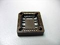
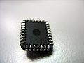
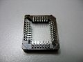
File:Plcc socket.jpg|... | File:Plcc socket.jpg|... | ||
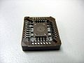
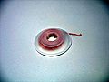
File:Plcc socket back side.jpg | |||
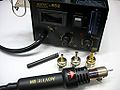
File:Desoldering station.jpg|... | File:Desoldering station.jpg|... | ||
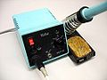
File:Soldering iron.jpg|... | File:Soldering iron.jpg|... | ||
File:Desoldering wick.jpg|... | File:Desoldering wick.jpg|... | ||
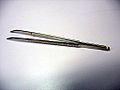
File:Tweezers.jpg|... | File:Tweezers.jpg|... | ||
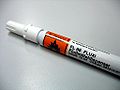
File:Flussmitteldispenser.jpg | |||
</gallery> | </gallery> | ||
| Line 26: | Line 28: | ||
<gallery> | <gallery> | ||
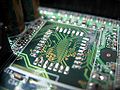
File:Soldered plcc rom chip.jpg|... | File:Soldered plcc rom chip.jpg|... | ||
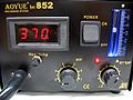
File:Desoldering station temperature.jpg|... | |||
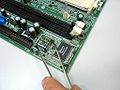
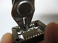
File:Holding dragging the chip with tweezers.jpg | |||
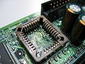
File:Pads after desoldering.jpg|... | File:Pads after desoldering.jpg|... | ||
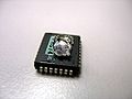
File:Rom chip desoldered front.jpg | |||
File:Rom chip after desoldering.jpg | |||
</gallery> | </gallery> | ||
| Line 33: | Line 39: | ||
<gallery> | <gallery> | ||
File:Pads cleaning.jpg | File:Pads cleaning.jpg | ||
File:Pads after cleaning.jpg | |||
</gallery> | </gallery> | ||
| Line 41: | Line 48: | ||
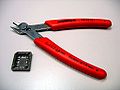
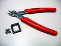
File:Cutting the plastic from the plcc socket.jpg|... | File:Cutting the plastic from the plcc socket.jpg|... | ||
File:Pliers2.jpg|... | File:Pliers2.jpg|... | ||
File:Plcc socket back side without plastic.jpg | |||
</gallery> | </gallery> | ||
| Line 46: | Line 54: | ||
<gallery> | <gallery> | ||
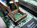
File:Fixating the socket on the pads.jpg | |||
File:Plcc socket soldered.jpg|... | File:Plcc socket soldered.jpg|... | ||
</gallery> | </gallery> | ||
Revision as of 17:13, 26 March 2009
Mainboards where the BIOS chip is soldered onto the board (and not in a socket) are usually problematic for coreboot developers and especially users, as one incorrectly flashed image will render the board unusable.
Requirements
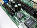
- A board with soldered-on (PLCC) chip
- Soldering iron
- A PLCC socket (SMD type)
- Desoldering station or heat gun
- Tweezers
- ...
-
...
-
-
...
-
...
-
...
-
...
-


Preparation
- Take a picture of the board and ROM chip. You might need that later in order to add the socket in the correct orientation.
Desolder or cut away the ROM chip
-
...
-
...
-
-
...
-
-


Clean the pads on the board


Prepare the PLCC socket
-
...
-
...
-
...
-


Solder the socket onto the board
-
-
...


Resources
- HOWO: replace a PLCC chip with a socket "ghetto style" (Tutorial for doing this without desoldering station by cutting the chip)
| I, the copyright holder of this work, hereby release it into the public domain. This applies worldwide.
In case this is not legally possible: |