File list
Jump to navigation
Jump to search
This special page shows all uploaded files.
| Date | Name | Thumbnail | Size | User | Description | Versions |
|---|---|---|---|---|---|---|
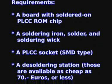
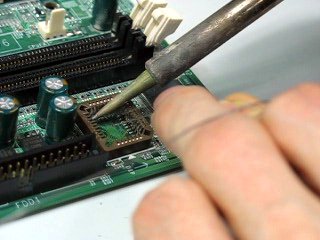
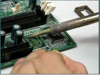
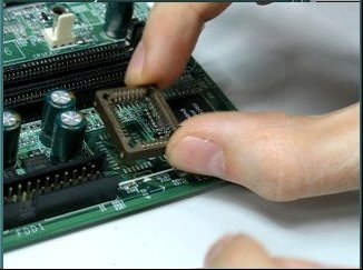
| 20:21, 30 March 2009 | Desoldering video 2.jpg (file) |  |
22 KB | Uwe | Desoldering video screenshot 2. Author: Uwe Hermann {{PD-self}} | 1 |
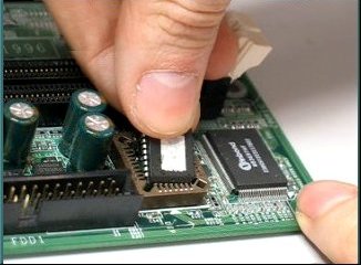
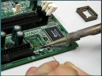
| 20:20, 30 March 2009 | Desoldering video 1.jpg (file) |  |
15 KB | Uwe | Desoldering video screenshot 1. Author: Uwe Hermann {{PD-self}} | 1 |
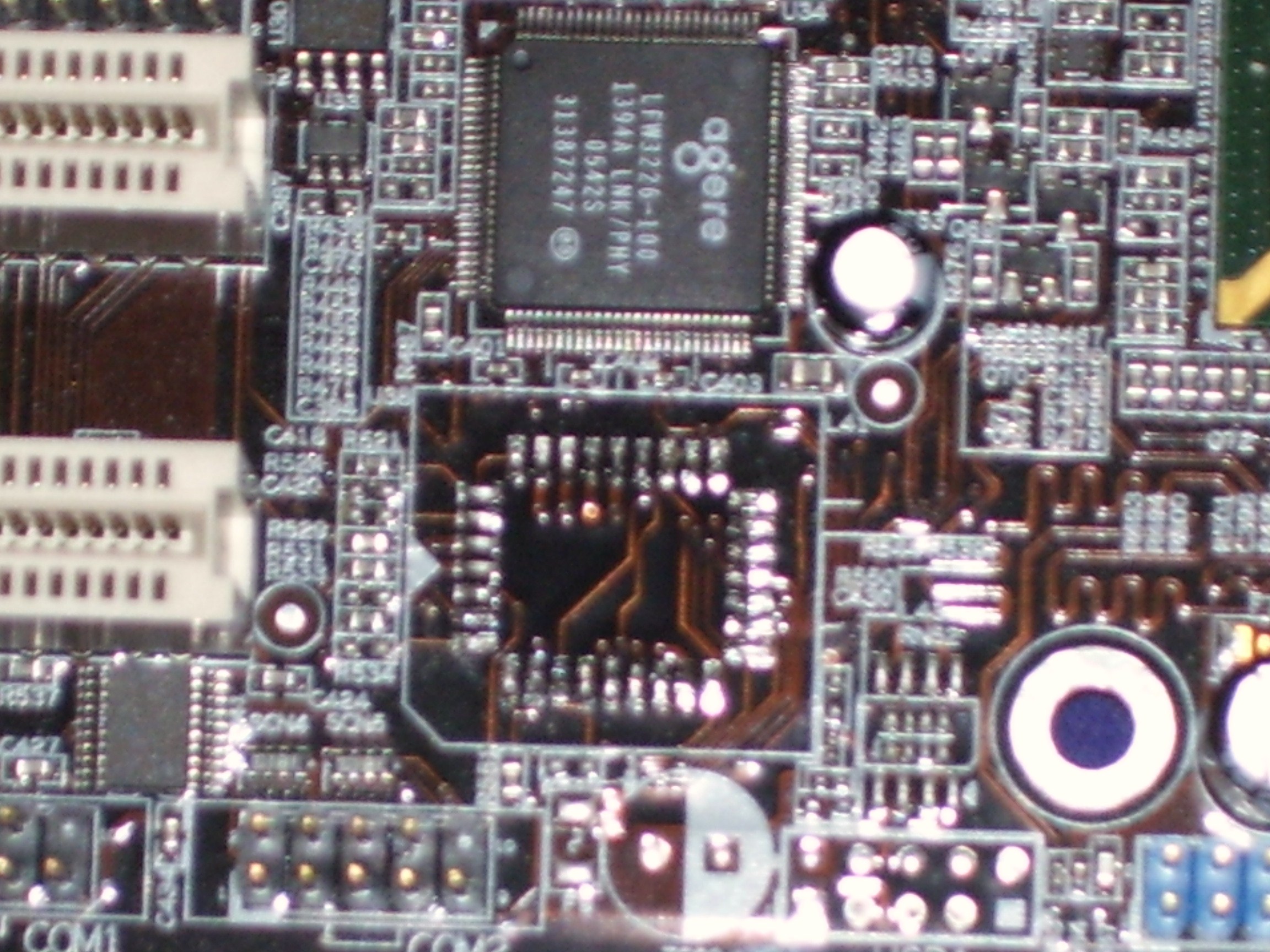
| 03:01, 30 March 2009 | Foil-hgun11.jpg (file) |  |
749 KB | Linux junkie | 11. Close up of the chipless board. Now your ready to clean it up and solder on a socket. | 1 |
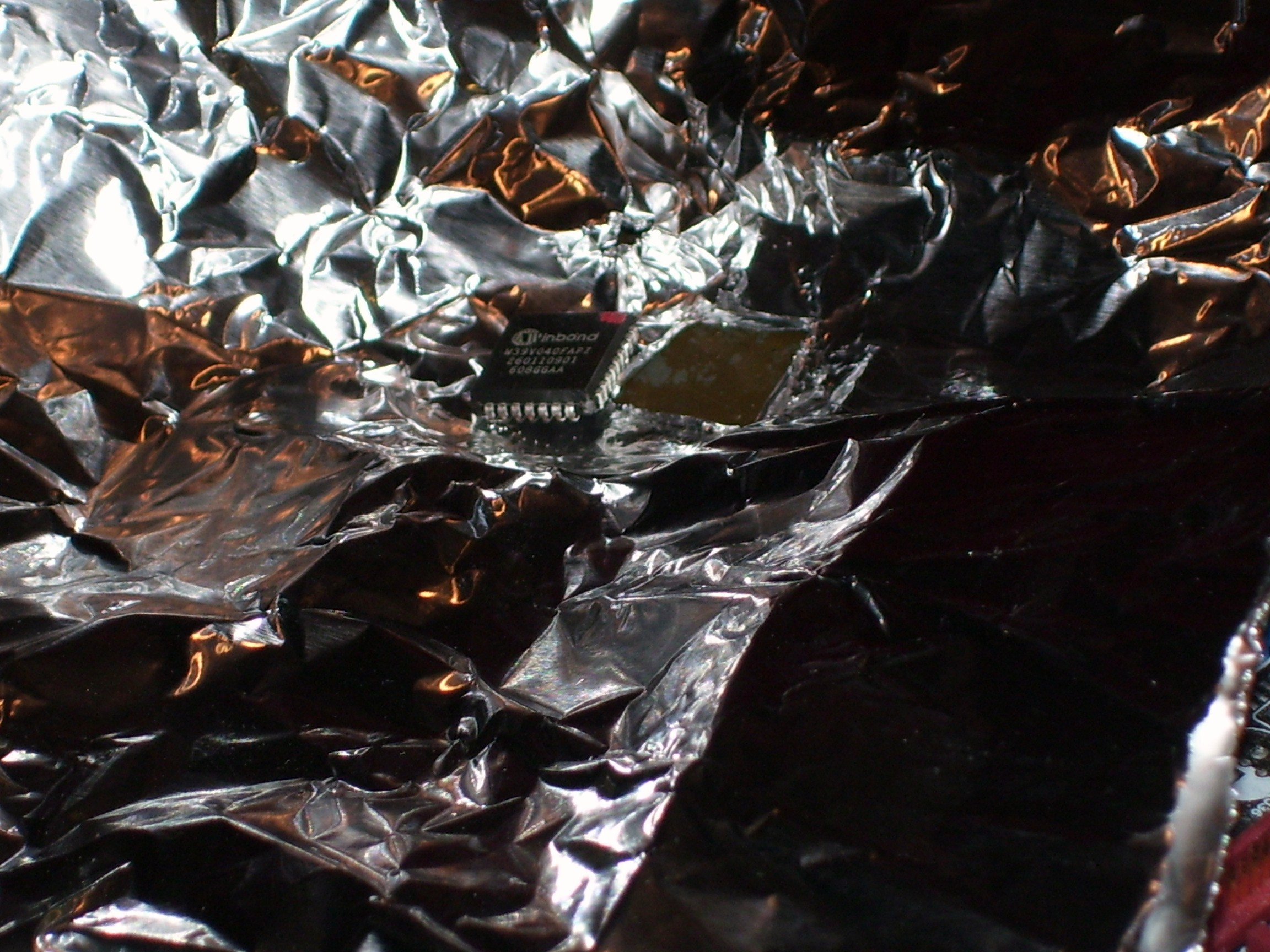
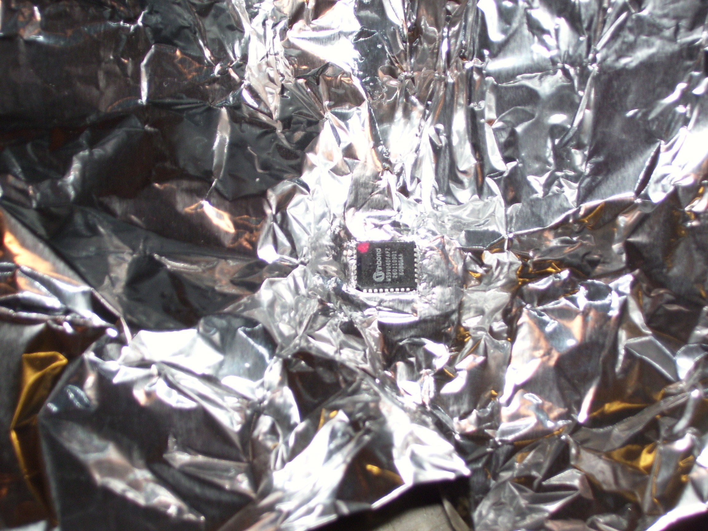
| 03:00, 30 March 2009 | Foil-hgun10.jpg (file) |  |
760 KB | Linux junkie | 10. Another shot of the foil and chip. | 1 |
| 02:59, 30 March 2009 | Foil-hgun9.jpg (file) |  |
672 KB | Linux junkie | 9. Shot with the foil and chip removed. | 1 |
| 02:58, 30 March 2009 | Foil-hgun8.jpg (file) |  |
892 KB | Linux junkie | 8. After a minute or two the chip will pretty much fall off. Use tweezers to remove. | 1 |
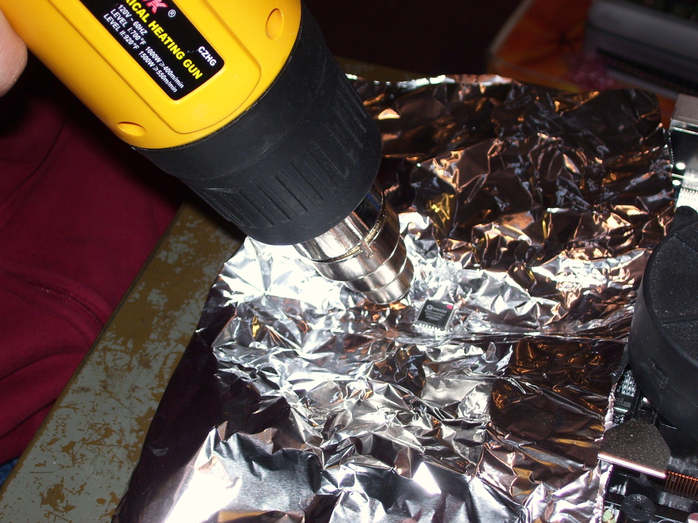
| 02:55, 30 March 2009 | Foil-hgun7.jpg (file) |  |
866 KB | Linux junkie | 7. Blow the heat at an angle to the side of the chip at the solder joints going around the chip in a circle. Never directly on top. | 1 |
| 02:53, 30 March 2009 | Foil-hgun6.jpg (file) |  |
830 KB | Linux junkie | 6. Close up of foil over chip. | 1 |
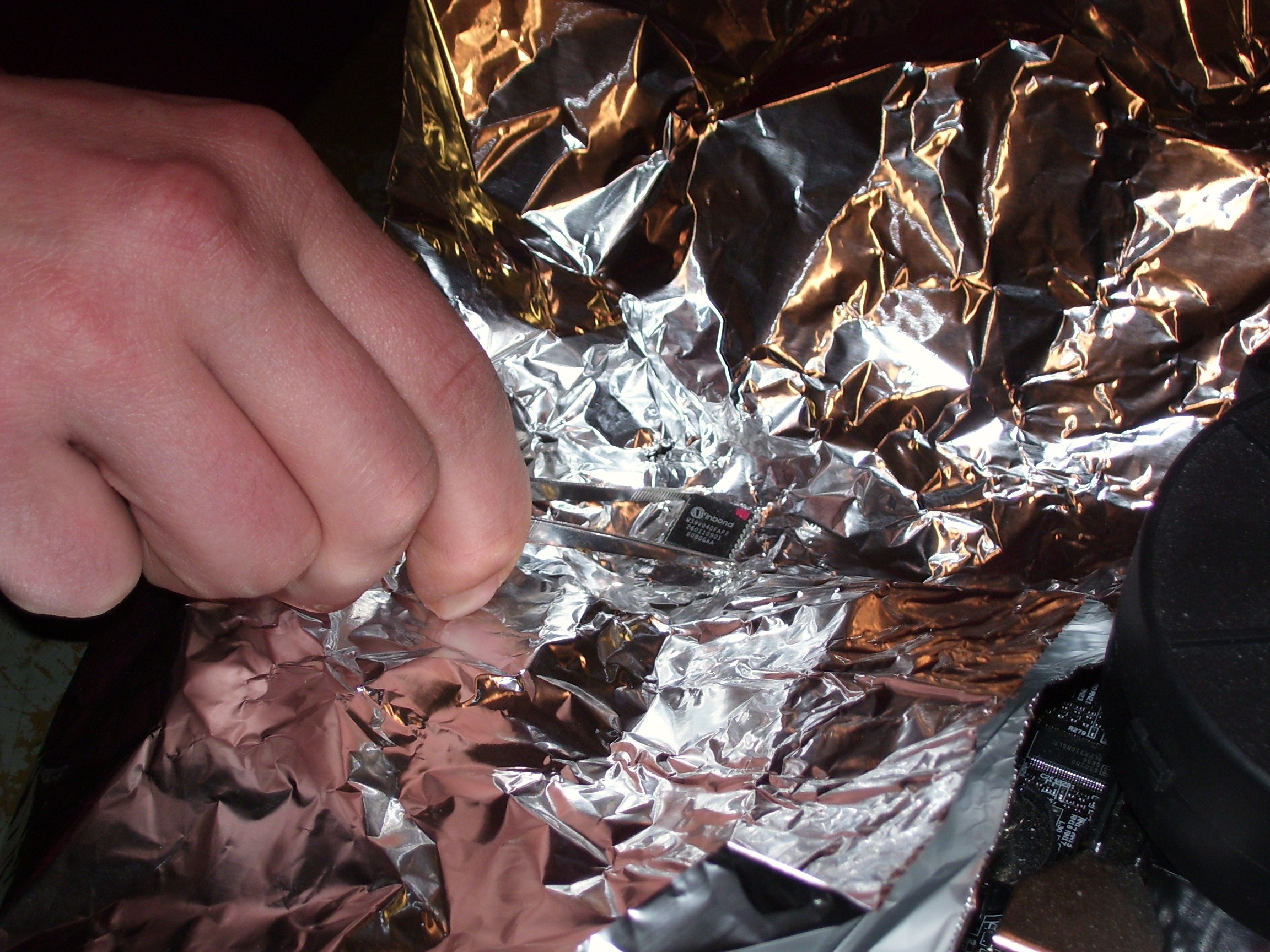
| 02:52, 30 March 2009 | Foil-hgun5.jpg (file) |  |
955 KB | Linux junkie | 5. Place the foil over the chip. | 1 |
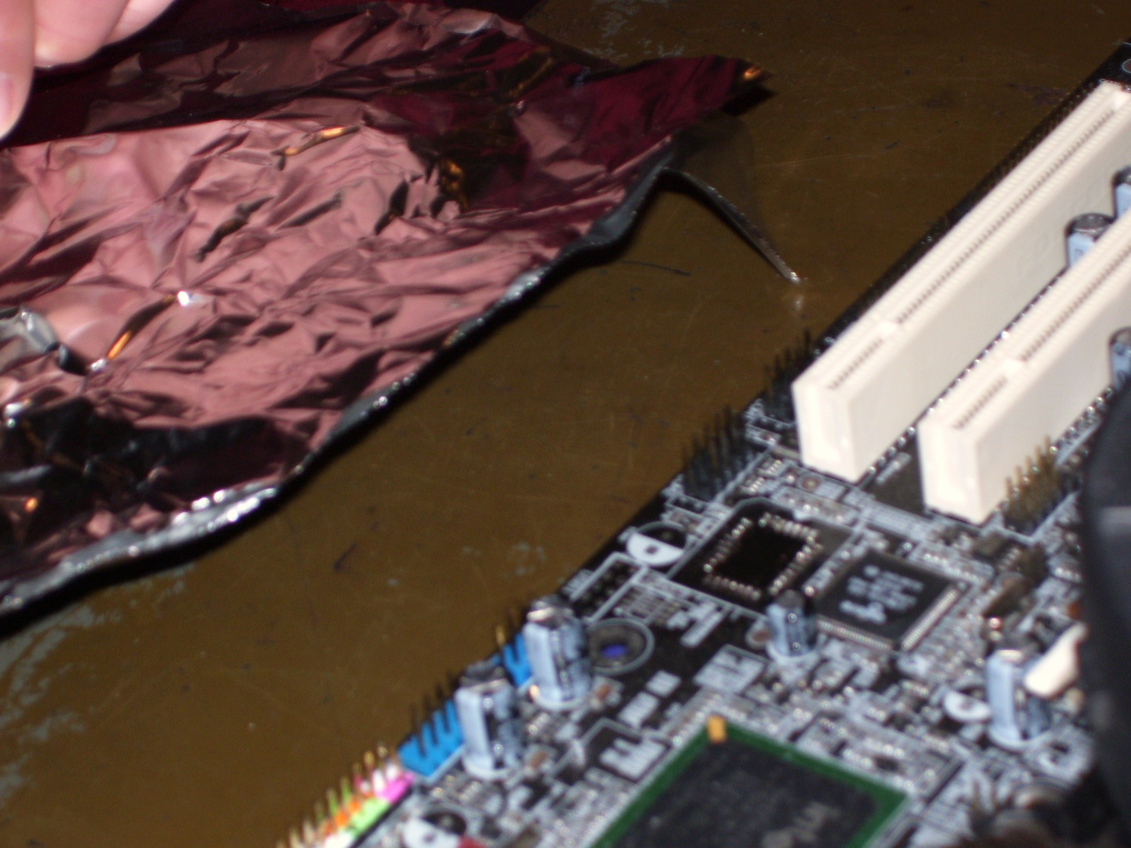
| 02:51, 30 March 2009 | Foil-hgun4.jpg (file) |  |
898 KB | Linux junkie | 4. Foil with chip cut out. | 1 |
| 02:49, 30 March 2009 | Foil-hgun3.jpg (file) |  |
840 KB | Linux junkie | 3. Cut out a rectangle out just the size of the chip. | 1 |
| 02:47, 30 March 2009 | Foil-hgun2.jpg (file) |  |
926 KB | Linux junkie | 2. Bend the foil over the chip for cut out lines. | 1 |
| 02:44, 30 March 2009 | Foil-hgun1.jpg (file) |  |
911 KB | Linux junkie | 1. Use a piece of aluminum foil and fold it in half (for double the protection) | 1 |
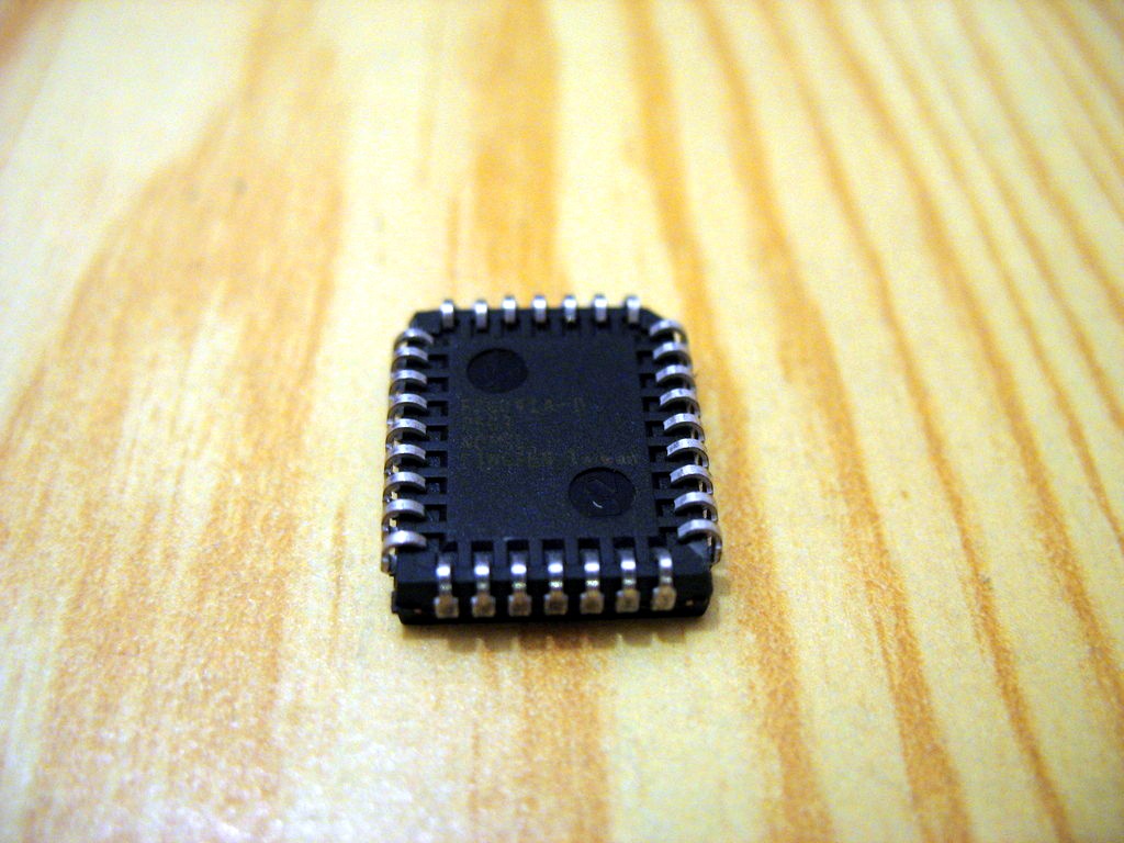
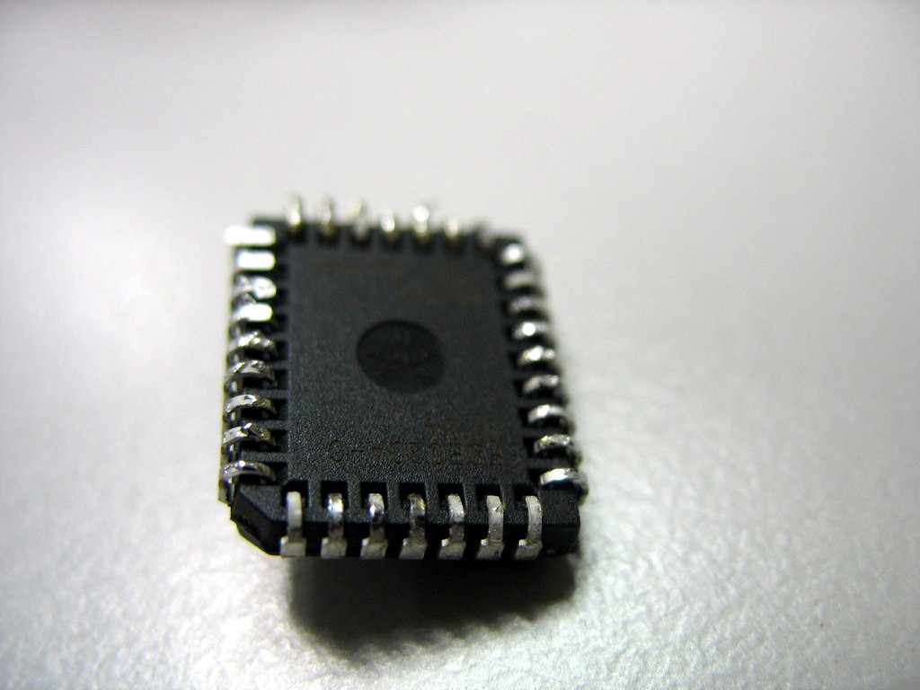
| 22:11, 27 March 2009 | Plcc32 chip back.jpg (file) |  |
150 KB | Uwe | PLCC32 chip. Author: Uwe Hermann {{PD-self}} | 1 |
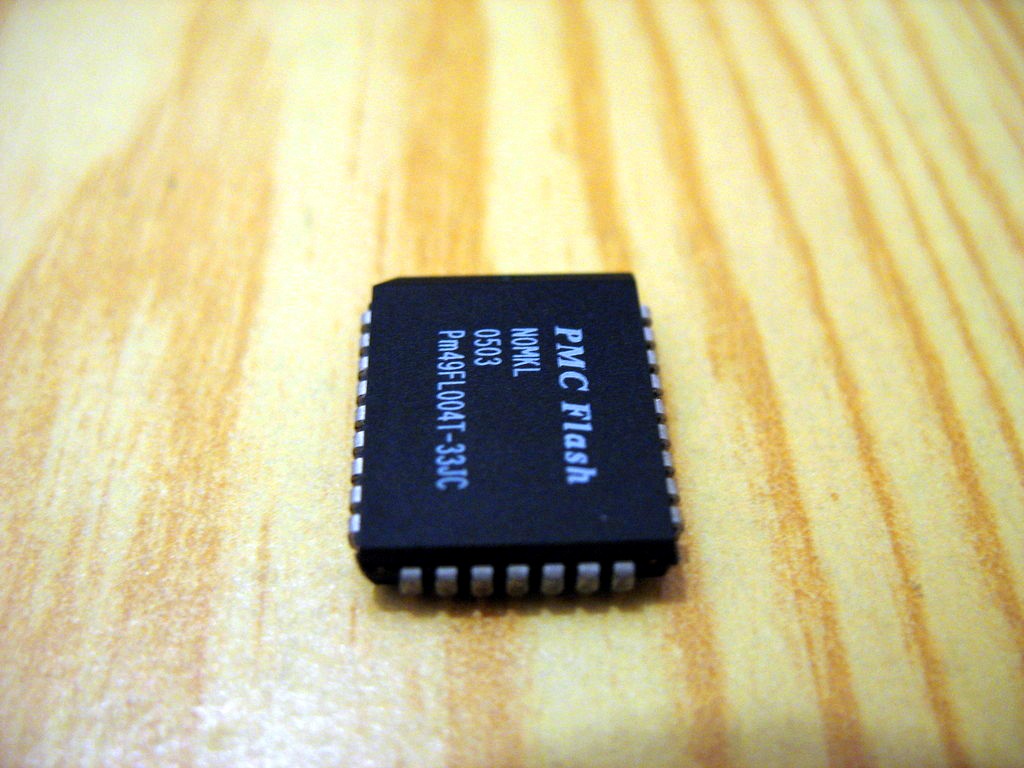
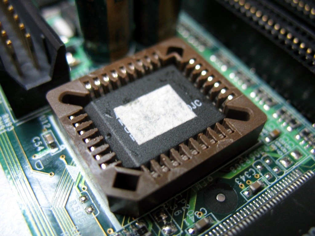
| 22:11, 27 March 2009 | Plcc32 chip.jpg (file) |  |
142 KB | Uwe | PLCC32 chip. Author: Uwe Hermann {{PD-self}} | 1 |
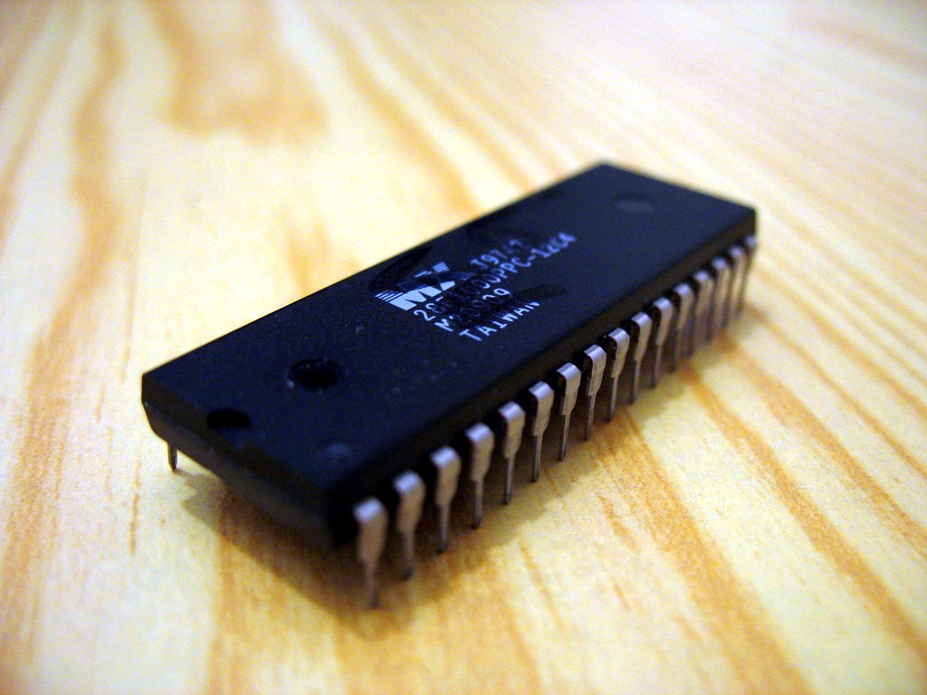
| 22:10, 27 March 2009 | Dip32 chip back.jpg (file) |  |
138 KB | Uwe | DIP32 chip, back. Author: Uwe Hermann {{PD-self}} | 1 |
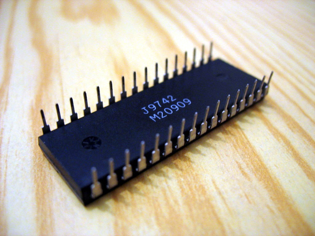
| 22:10, 27 March 2009 | Dip32 chip.jpg (file) |  |
136 KB | Uwe | DIP32 chip. Author: Uwe Hermann {{PD-self}} | 1 |
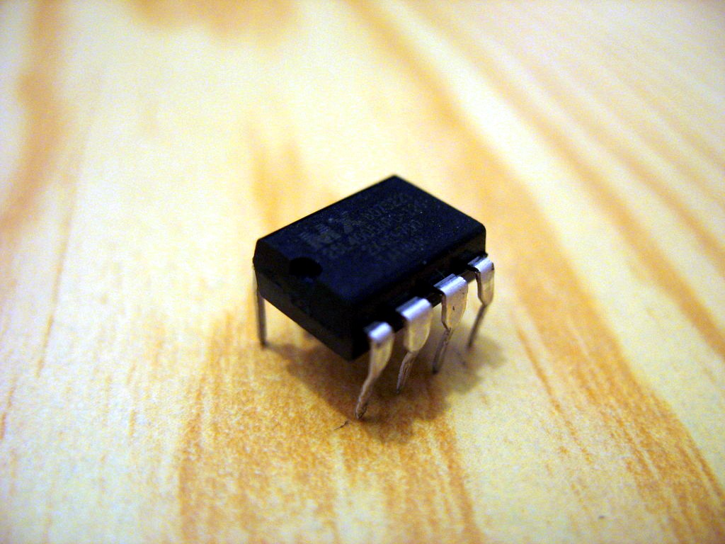
| 22:09, 27 March 2009 | Dip8 chip back.jpg (file) |  |
135 KB | Uwe | Dip8 chip, back. Author: Uwe Hermann {{PD-self}} | 1 |
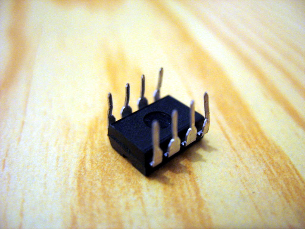
| 22:09, 27 March 2009 | Dip8 chip.jpg (file) |  |
140 KB | Uwe | DIP8 chip. Author: Uwe Hermann {{PD-self}} | 1 |
| 02:51, 27 March 2009 | Test the socket.jpg (file) |  |
20 KB | Uwe | Testing the socket. Author: Uwe Hermann {{PD-self}} | 1 |
| 02:51, 27 March 2009 | Soldering the socket.jpg (file) |  |
19 KB | Uwe | Soldering the socket. Author: Uwe Hermann {{PD-self}} | 1 |
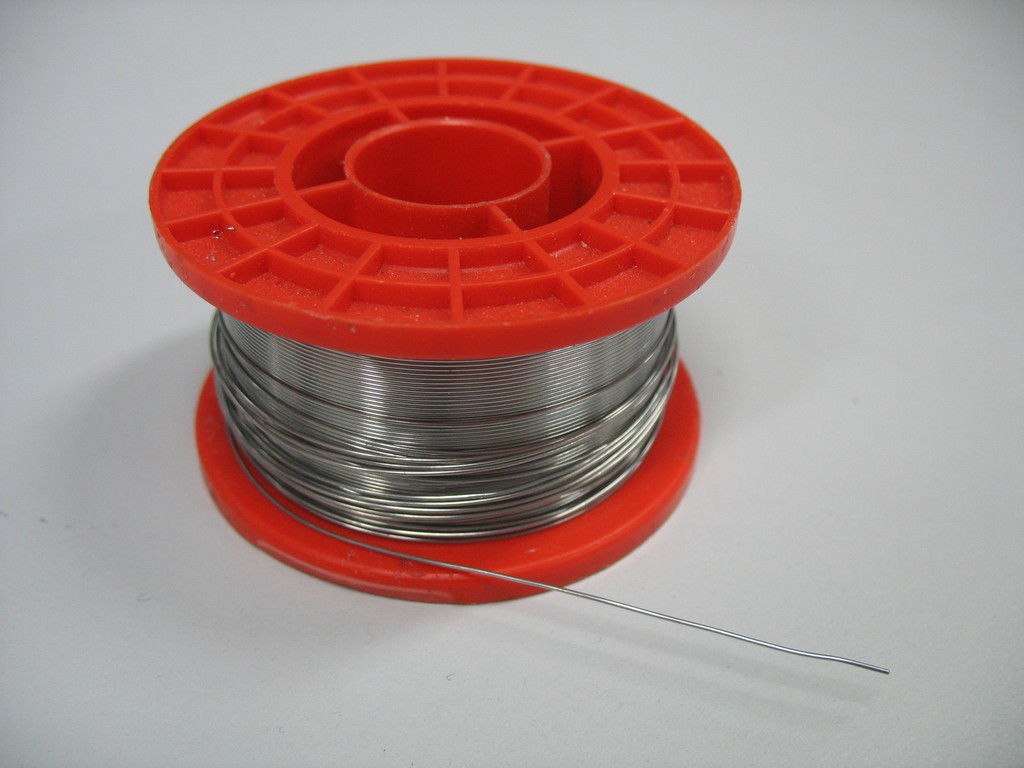
| 02:50, 27 March 2009 | Solder.jpg (file) |  |
118 KB | Uwe | Solder. Author: Uwe Hermann {{PD-self}} | 1 |
| 02:50, 27 March 2009 | Socket with chip.jpg (file) |  |
171 KB | Uwe | A chip in our new socket. Author: Uwe Hermann {{PD-self}} | 1 |
| 02:50, 27 March 2009 | Prepare two pads2.jpg (file) |  |
23 KB | Uwe | Prepare a pad in the opposite corner of the socket. Author: Uwe Hermann {{PD-self}} | 1 |
| 02:49, 27 March 2009 | Prepare two pads.jpg (file) |  |
22 KB | Uwe | Prepare a pad in one corner of the socket. Author: Uwe Hermann {{PD-self}} | 1 |
| 02:49, 27 March 2009 | Place plcc socket.jpg (file) |  |
20 KB | Uwe | Place the socket on the pads. Author: Uwe Hermann {{PD-self}} | 1 |
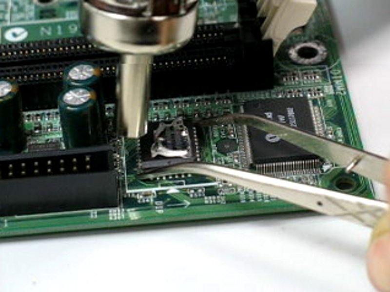
| 02:48, 27 March 2009 | Desoldering the chip.jpg (file) |  |
66 KB | Uwe | Desoldering the chip. Author: Uwe Hermann {{PD-self}} | 1 |
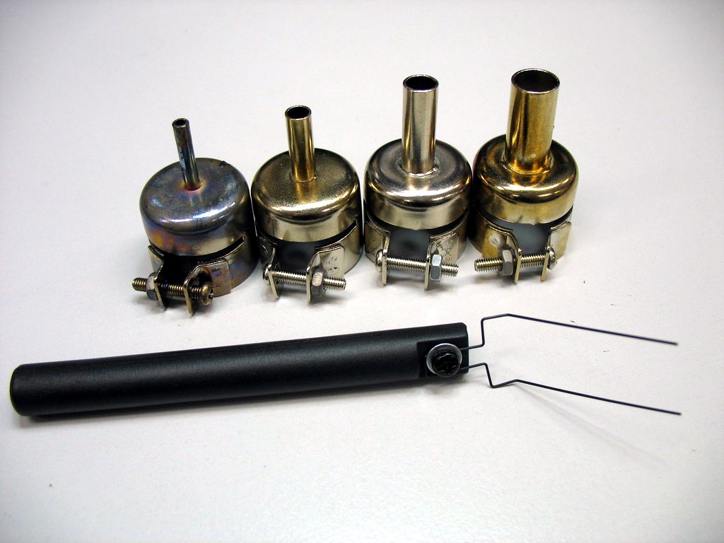
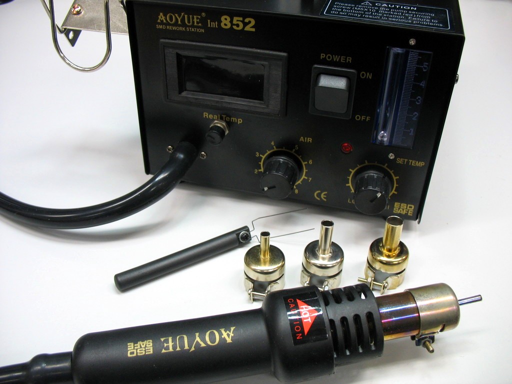
| 02:47, 27 March 2009 | Desoldering station accessories.jpg (file) |  |
127 KB | Uwe | Desoldering station accessories. Author: Uwe Hermann {{PD-self}} | 1 |
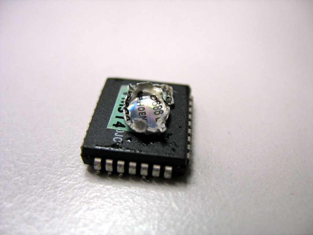
| 17:09, 26 March 2009 | Rom chip desoldered front.jpg (file) |  |
101 KB | Uwe | ROM chip after desoldering, back side. Author: Uwe Hermann {{PD-self}} | 1 |
| 17:09, 26 March 2009 | Rom chip after desoldering.jpg (file) |  |
104 KB | Uwe | ROM chip after desoldering. Author: Uwe Hermann {{PD-self}} | 1 |
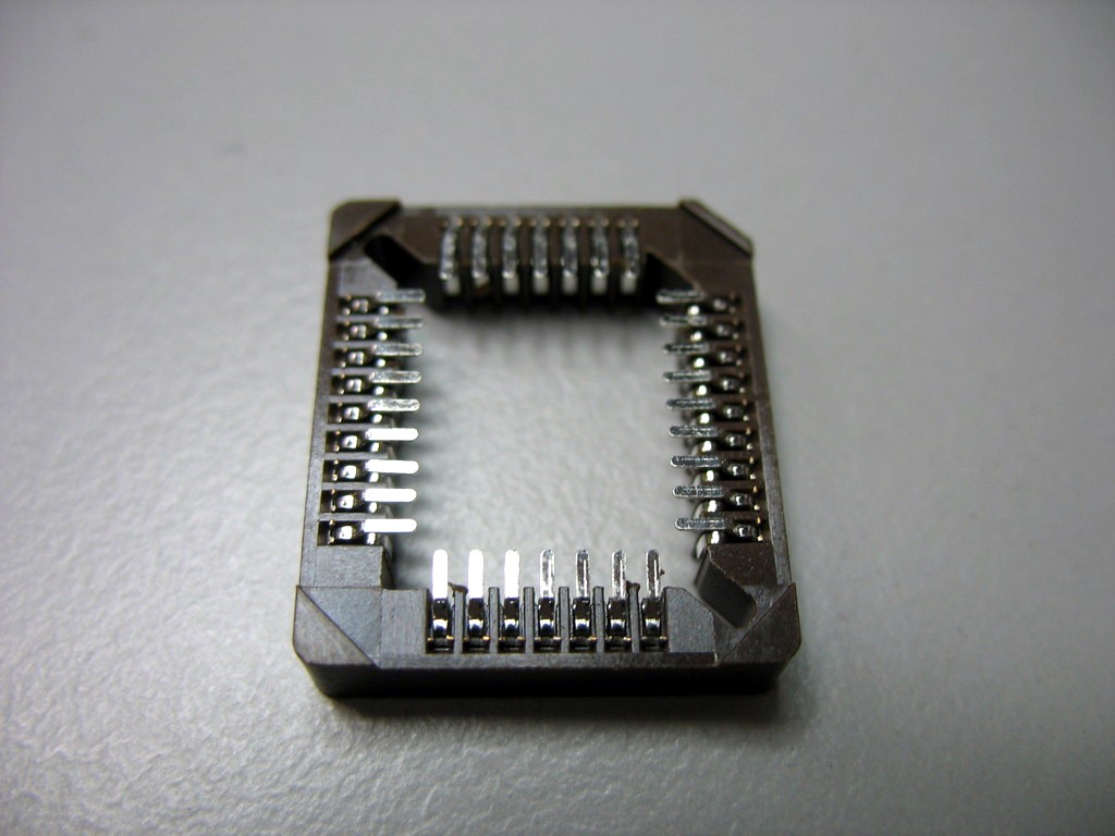
| 17:09, 26 March 2009 | Plcc socket back side without plastic.jpg (file) |  |
108 KB | Uwe | PLCC socket, back side, without middle plastic. Author: Uwe Hermann {{PD-self}} | 1 |
| 17:08, 26 March 2009 | Plcc socket back side.jpg (file) |  |
111 KB | Uwe | PLCC socket, back side. Author: Uwe Hermann {{PD-self}} | 1 |
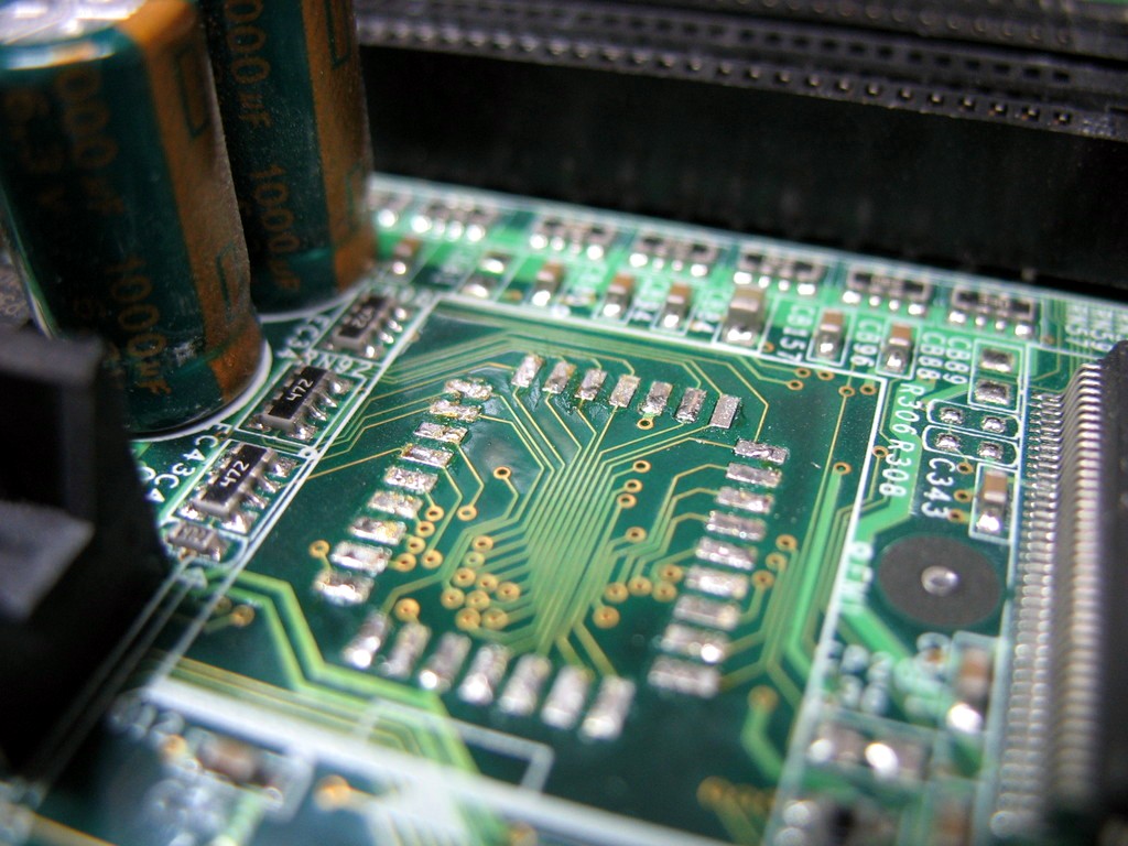
| 17:08, 26 March 2009 | Pads after cleaning.jpg (file) |  |
181 KB | Uwe | Pads after cleaning. Author: Uwe Hermann {{PD-self}} | 1 |
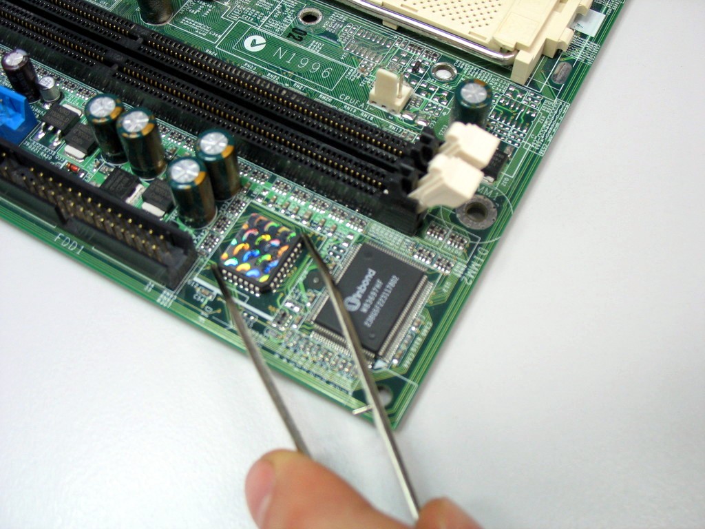
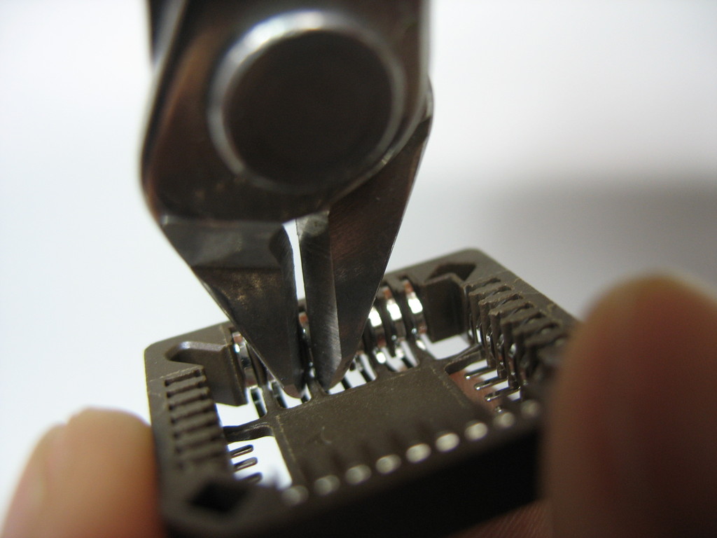
| 17:08, 26 March 2009 | Holding dragging the chip with tweezers.jpg (file) |  |
187 KB | Uwe | Holding and/or dragging (slightly) the chip using tweezers. Author: Uwe Hermann {{PD-self}} | 1 |
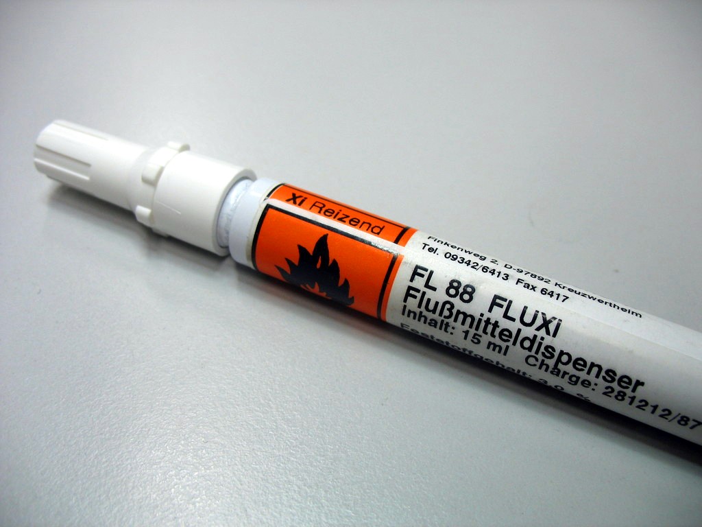
| 17:07, 26 March 2009 | Flussmitteldispenser.jpg (file) |  |
115 KB | Uwe | Flussmitteldispenser. Author: Uwe Hermann {{PD-self}} | 1 |
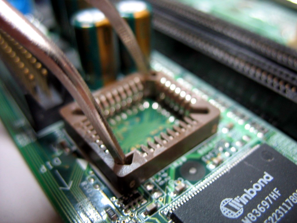
| 17:07, 26 March 2009 | Fixating the socket on the pads.jpg (file) |  |
145 KB | Uwe | Fixating the PLCC socket on the pads using tweezers. Author: Uwe Hermann {{PD-self}} | 1 |
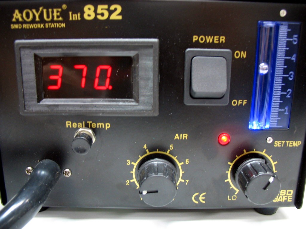
| 17:07, 26 March 2009 | Desoldering station temperature.jpg (file) |  |
144 KB | Uwe | Desoldering station temperature settings. Author: Uwe Hermann {{PD-self}} | 1 |
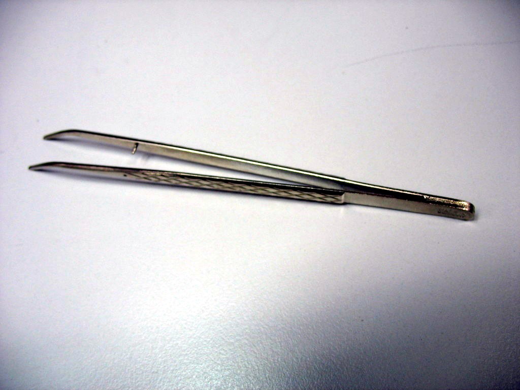
| 16:34, 26 March 2009 | Tweezers.jpg (file) |  |
101 KB | Uwe | Tweezers. Author: Uwe Hermann {{PD-self}} | 1 |
| 16:34, 26 March 2009 | Soldering iron.jpg (file) |  |
125 KB | Uwe | Soldering iron. Author: Uwe Hermann {{PD-self}} | 1 |
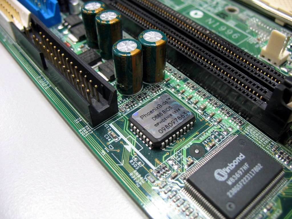
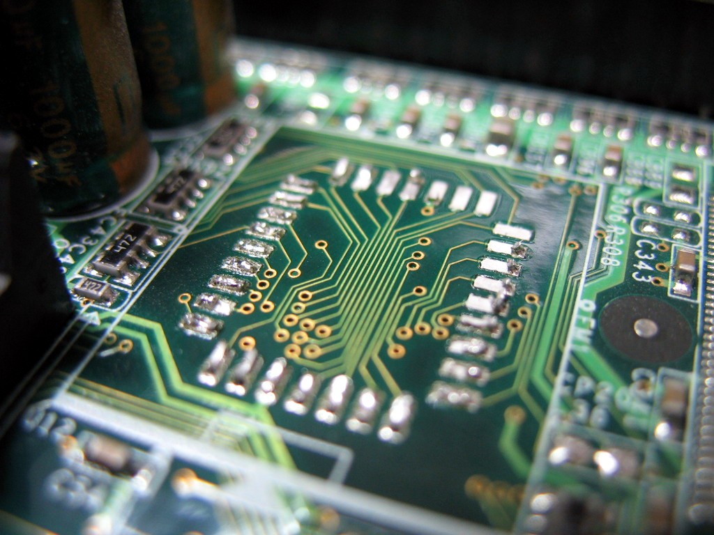
| 16:33, 26 March 2009 | Soldered plcc rom chip.jpg (file) |  |
225 KB | Uwe | Soldered PLCC ROM chip on some random board. Author: Uwe Hermann {{PD-self}} | 1 |
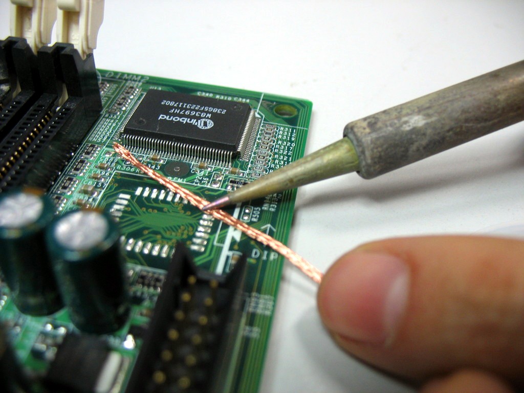
| 16:28, 26 March 2009 | Pads cleaning.jpg (file) |  |
146 KB | Uwe | Cleaning the pads with desoldering wick. Author: Uwe Hermann {{PD-self}} | 1 |
| 16:28, 26 March 2009 | Cutting the plastic from the plcc socket.jpg (file) |  |
107 KB | Uwe | Cutting the plastic from the PLCC socket for easier soldering. Author: Uwe Hermann {{PD-self}} | 1 |
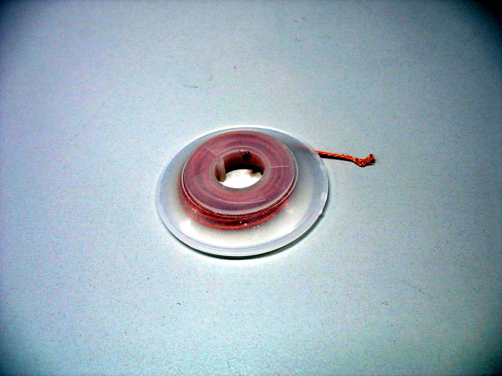
| 16:27, 26 March 2009 | Desoldering wick.jpg (file) |  |
137 KB | Uwe | Desoldering wick. Author: Uwe Hermann {{PD-self}} | 1 |
| 16:26, 26 March 2009 | Pads after desoldering.jpg (file) |  |
177 KB | Uwe | Pads after desoldering the ROM chip. Author: Uwe Hermann {{PD-self}} | 1 |
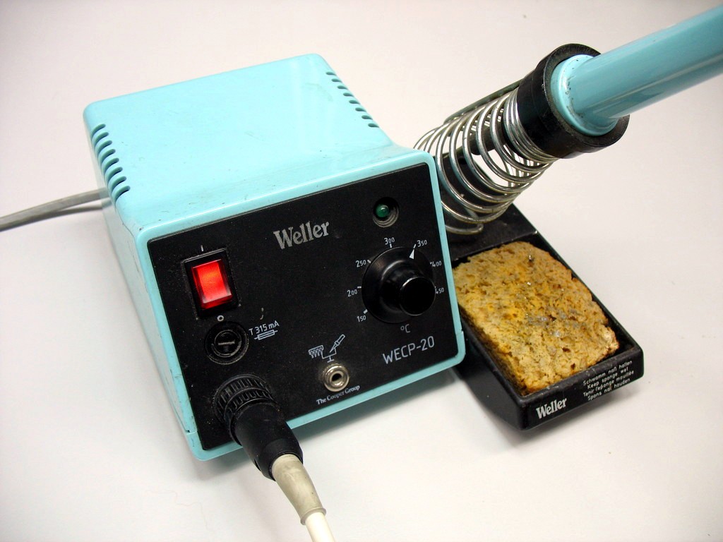
| 16:25, 26 March 2009 | Desoldering station.jpg (file) |  |
138 KB | Uwe | Cheap desoldering station. Author: Uwe Hermann {{PD-self}} | 1 |
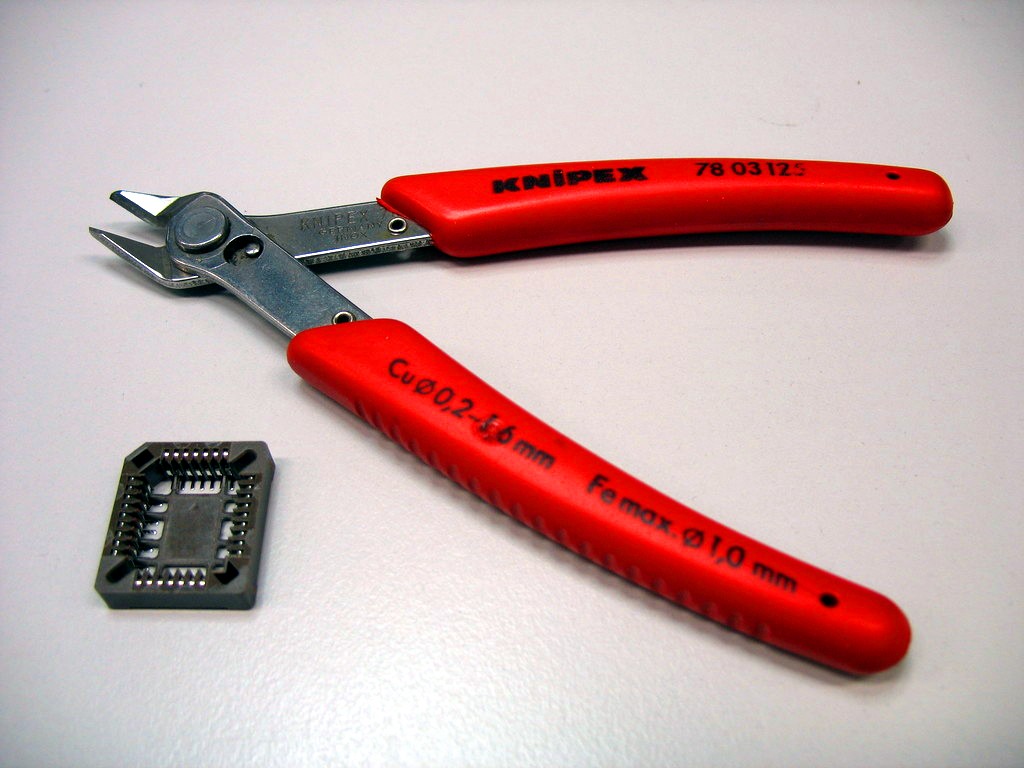
| 16:16, 26 March 2009 | Pliers2.jpg (file) |  |
130 KB | Uwe | Pliers and a modified PLCC socket (removed middle part for easier soldering). Author: Uwe Hermann {{PD-self}} | 1 |
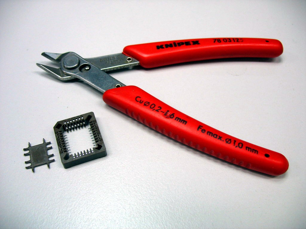
| 16:16, 26 March 2009 | Pliers1.jpg (file) |  |
120 KB | Uwe | Pliers and a PLCC socket. Author: Uwe Hermann {{PD-self}} | 1 |
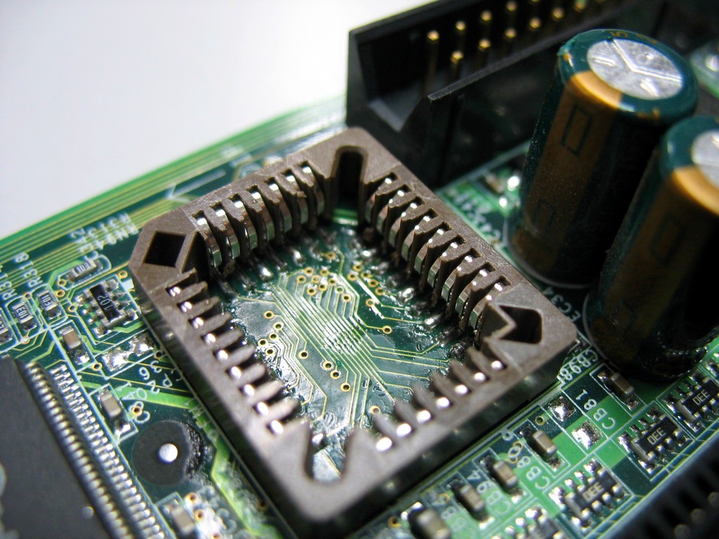
| 16:15, 26 March 2009 | Plcc socket soldered.jpg (file) |  |
198 KB | Uwe | Done. PLCC socket successfull soldered onto the board. Author: Uwe Hermann {{PD-self}} | 1 |
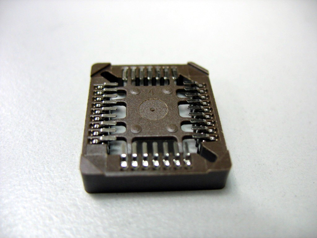
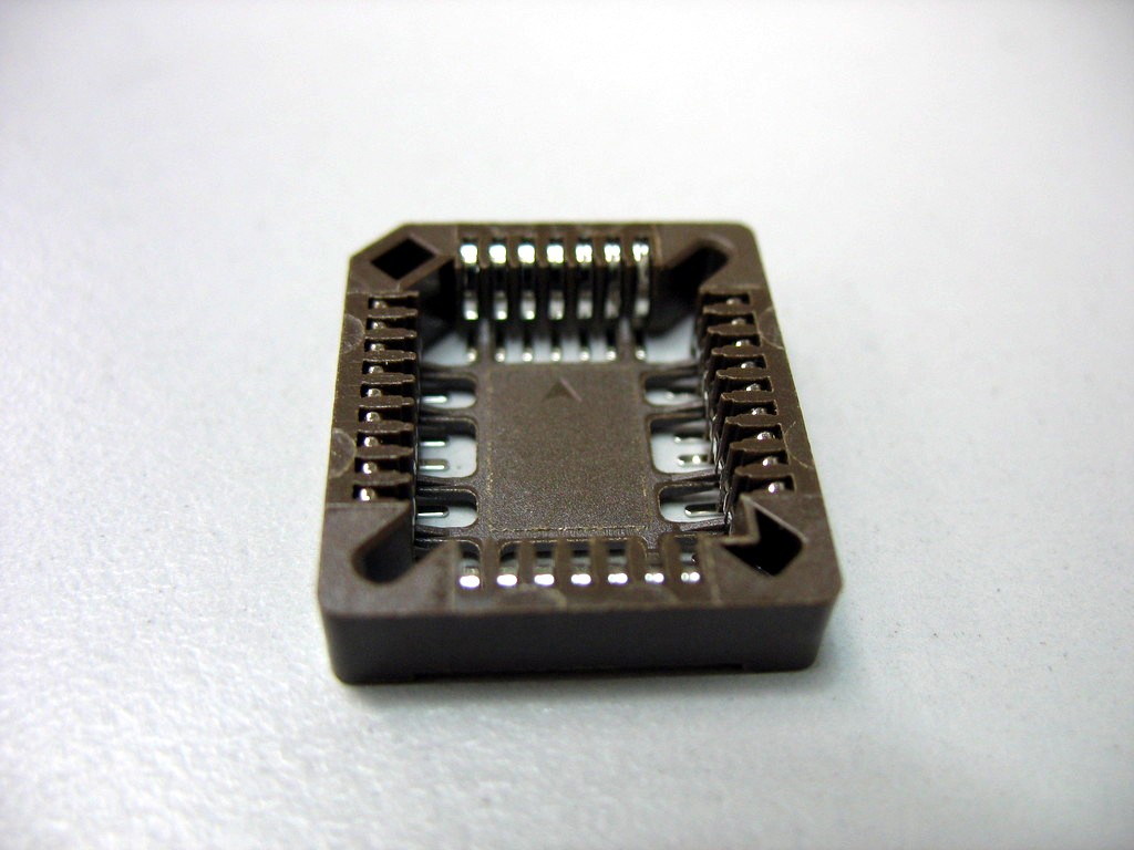
| 16:14, 26 March 2009 | Plcc socket.jpg (file) |  |
110 KB | Uwe | A PLCC socket (SMD type). Author: Uwe Hermann {{PD-self}} | 1 |
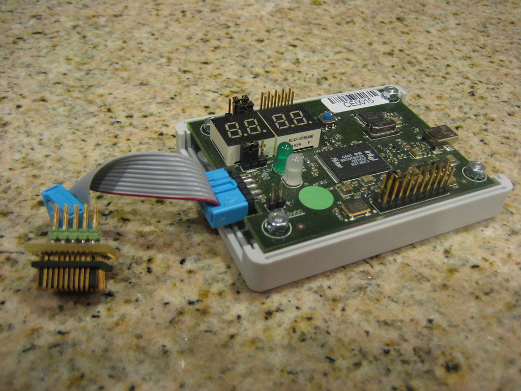
| 11:29, 22 March 2009 | Artec dongle.jpg (file) |  |
261 KB | Stepan | Picture of Artec Group dongle with Konsult Stuge's PLCC adapter. | 1 |