Developer Manual: Difference between revisions
Whiterocker (talk | contribs) (describe the path an Intel architecture mainboard takes from reset to payload execution) |
(Docs.) |
||
| Line 136: | Line 136: | ||
=== CuteCom === | === CuteCom === | ||
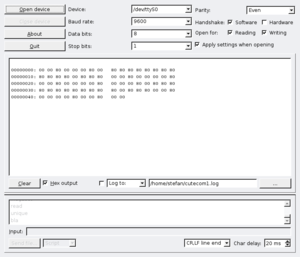
This is an easy to use serial-terminal-program which is even able to write all communication into a log-file. It needs a computer with installed Qt-libs.[[Image:CuteCom.png|thumb|left]] | This is an easy to use serial-terminal-program which is even able to write all communication into a log-file. It needs a computer with installed Qt-libs. | ||
[[Image:CuteCom.png|thumb|left]] | |||
<br clear="all" /> | |||
== Documentation and datasheets == | |||
=== Useful hardware/concepts documentation for developers === | |||
These external documents and slides explain fundamental concepts of hardware that coreboot supports. | |||
==== Interrupts ==== | |||
* [http://www.bsdcan.org/2007/schedule/attachments/13-PCI_Interrupts_for_x86_Machines_under_FreeBSD_John_Baldwin PCI Interrupts on x86 machines] from John Baldwin | |||
* [http://www.microsoft.com/whdc/system/CEC/ACPI-MP.mspx PCI IRQ Routing on a Multiprocessor ACPI System] at Microsoft's Windows Hardware Developer Central | |||
=== Specific datasheets === | |||
TODO. | |||
{{GPL}} | {{GPL}} | ||
Revision as of 18:02, 18 March 2008
Introduction
This manual is intended for aspiring coreboot developers to help them get up to speed with the code base and the tasks required to add support for new chipsets, devices, and mainboards. It currently covers coreboot v2, but will be extended to also cover the development version coreboot v3 later.
Hardware Overview
Intel Architecture
Hardware Reset
|
The first instruction that is fetched and executed following a hardware reset is located at physical address 0xFFFFFFF0. This address is 16 bytes below the processors uppermost physical address. The EPROM containing the software-initialization code must be located at this address. The address 0xFFFFFFF0 is beyond the 1-MByte addressable range of the processor while in real-address mode. The processor is initialized to this starting address as follows. The CS register has two parts: the visible segment selector part and the hidden base address part. In real-address mode, the base address is normally formed by shifting the 16-bit segment selector value 4 bits to the left to produce a 20-bit base address. However, during a hardware reset, the segment selector in the CS register is loaded with 0xF000 and the base address is loaded with 0xFFFF0000. The starting address is thus formed by adding the base address to the value in the EIP register (that is, 0xFFFF0000 + 0xFFF0 = 0xFFFFFFF0). The first time the CS register is loaded with a new value after a hardware reset, the processor will follow the normal rule for address translation in real-address mode (that is, [CS base address = CS segment selector * 16]). To insure that the base address in the CS register remains unchanged until the EPROM based software-initialization code is completed, the code must not contain a far jump or far call or allow an interrupt to occur (which would cause the CS selector value to be changed). |
FWH/LPC Flash Memory
Modern mainboards are often equipped with Firmware Hub (FWH) or Low Pin Count (LPC) flash memory used to store the system bootloader ("BIOS"). Execution begins by fetching instructions 16 bytes below the flash memory's uppermost physical address.
coreboot Overview
View From The CPU: Intel Architecture
- at
0xFFFFFFF0, start execution atreset_vectorfrom src/cpu/x86/16bit/reset16.inc, which simply jumps to_start _startfrom src/cpu/x86/16bit/entry16.inc, invalidates the TLBs, sets up a GDT for selector 0x08 (code) and 0x10 (data), switches to protected mode, and jumps to__protected_start(setting the CS to the new selector 0x08). The selectors provide full flat access to the entire physical memory map.__protected_startfrom src/cpu/x86/32bit/entry32.inc, sets all other segment registers to the 0x10 selector- execution continues with various
mainboardinitfragments:__fpu_startfrom cpu/x86/fpu/enable_fpu.inc(unlabeled)from cpu/x86/sse/enable_sse.inc- some CPUs enable their on-chip cache to be used temporarily as a scratch RAM (stack), e.g. cpu/amd/model_lx/cache_as_ram.inc
- the final
mainboardinitfragment is mainboard-specific, in 'C', called auto.c (or cache_as_ram_auto.c). It is compiled with 'romcc', and it includes and uses other C-code fragments for:- initializing MSRs, MTTRs, APIC
- setting up the Southbridge minimally ("early setup")
- setting up SuperIO serial
- initializing the console
- initializing RAM controller and RAM itself
- execution continues at
__mainfrom src/arch/i386/init/crt0.S.lb, where the non-romcc 'C' coreboot code is copied (possibly decompressed) to RAM, then the RAM entry point is jumped to. - the RAM entry point is
_startarch/i386/lib/c_start.S, where new descriptor tables are set up, the stack and BSS are cleared, the IDT is initialized, andhardwaremain( )is called (operation is now full 32-bit protected mode 'C' program with stack) hardwaremain( )is from boot/hardwaremain.c, the console is initialized, devices are enumerated and initialized, configured and enabled- the payload is called, either via
elfboot( )from boot/elfboot.c, orfilo( )from boot/filo.c
Serial output and the Super I/O
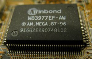
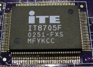
The Super I/O is a chip found on most of today's mainboards which is — among other things — responsible for the serial ports of the mainboard (e.g. COM1, COM2). This chip is usually the first thing you'll want to support, as it's required to get serial debugging output from the mainboard (via a null-modem cable and the proper software, e.g. minicom or CuteCom).


The steps for adding support for a new Super I/O chip are:
- Add a directory src/superio/vendor/device (e.g. src/superio/winbond/w83627ehg).
- In that directory, add a file device_early_serial.c (e.g. w83627ehg_early_serial.c). This file will be responsible to setup a serial port on the mainboard so that you can get serial debugging output. This will work even before the RAM is initialized, thus is useful/required for debugging the RAM initialization process.
- In this file you now declare a function device_enable_serial() which enables the requested serial port. Example:
 static void w83627ehg_enable_serial(device_t dev, unsigned int iobase)
 {
        pnp_enter_ext_func_mode(dev);
        pnp_set_logical_device(dev);
        pnp_set_enable(dev, 0);
        pnp_set_iobase(dev, PNP_IDX_IO0, iobase);
        pnp_set_enable(dev, 1);
        pnp_exit_ext_func_mode(dev);
 }
- Mainboards which have this Super I/O chip, will call this function in their auto.c or cache_as_ram_auto.c file. Example:
 #include "superio/winbond/w83627ehg/w83627ehg_early_serial.c"
 [...]
 #define SERIAL_DEV PNP_DEV(0x2e, W83627EHG_SP1)
 [...]
 w83627ehg_enable_dev(SERIAL_DEV, TTYS0_BASE);
 uart_init();
 console_init();
- Whether the Super I/O is at config address 0x2e (the usual case) or 0x4e (or some other address) is mainboard-dependent. You can find out the address by running superiotool.
Northbridge
RAM init
Resources:
SDRAM:
- Intel SPD Standard
- Micron 512 MB SDRAM Datasheet (PDF) -- contains some helpful explanations
DDR SDRAM:
- JEDEC DDR SPD Standard (PDF)
- Understanding DDR Serial Presence Detect (SPD) Table
- Micron DDR400 Datasheet
DDR2 SDRAM
DDR3 SDRAM
Southbridge
Mainboard
Config.lb
The mainboard config.lb contains many build and platform configuration settings. One of the most important items is the mainboard device list.
A device needs to be listed in the mainboard config.lb if it requires more setup than standard PCI initialization (resource allocation). Typically, that includes the CPU, northbridge, southbridge, and SIO. These devices are usually required for system specific configuration as well as indicate the system bus structure (pci_domain).
When a device in config.lb is found during the coreboot PCI/system scan process the functions to do customized initialization are called via the device_operations and the chip_operations structures. You will find these structures in the devices source files.
Options.lb
irq_table.c
Creating a new Target
To create a new mainboard target you have to add several files.
- Multiple files in src/mainboard/vendorname/mainboardname (replace vendorname and mainboardname, of course).
- A file targets/vendorname/mainboardname/Config.lb which specifies a few target-specific config options, e.g. the ROM chip size, the payload, etc.
Miscellaneous Tips
minicom
Minicom is not just a serial terminal. It was written long before the internet existed and electronic communication was only possible with a modem to a mailbox-computer. Minicom is written with the ncurses library and provides its magic via a text interface. Other than logging, it provides z-modem up- and download-capability.
CuteCom
This is an easy to use serial-terminal-program which is even able to write all communication into a log-file. It needs a computer with installed Qt-libs.

Documentation and datasheets
Useful hardware/concepts documentation for developers
These external documents and slides explain fundamental concepts of hardware that coreboot supports.
Interrupts
- PCI Interrupts on x86 machines from John Baldwin
- PCI IRQ Routing on a Multiprocessor ACPI System at Microsoft's Windows Hardware Developer Central
Specific datasheets
TODO.

|
This work is free software; you can redistribute it and/or modify it under the terms of the GNU General Public License as published by the Free Software Foundation; either version 2 of the License, or any later version. This work is distributed in the hope that it will be useful, but WITHOUT ANY WARRANTY; without even the implied warranty of MERCHANTABILITY or FITNESS FOR A PARTICULAR PURPOSE. See the GNU General Public License for more details. |