Soldering a socket on your board
The wiki is being retired!
Documentation is now handled by the same processes we use for code: Add something to the Documentation/ directory in the coreboot repo, and it will be rendered to https://doc.coreboot.org/. Contributions welcome!
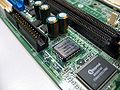
Mainboards where the BIOS chip is soldered onto the board (and not in a socket) are usually problematic for coreboot developers and especially users, as one incorrectly flashed image will render the board unusable.
Requirements
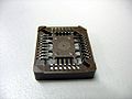
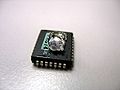
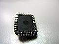
- A board with soldered-on (PLCC) chip
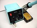
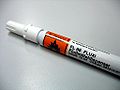
- Soldering iron
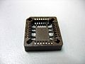
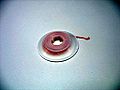
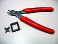
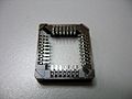
- A PLCC socket (SMD type)
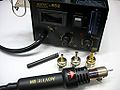
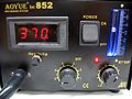
- Desoldering station or heat gun
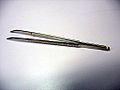
- Tweezers
- ...
-
...
-
-
...
-
...
-
...
-
...
-


Preparation
- Take a picture of the board and ROM chip. You might need that later in order to add the socket in the correct orientation.
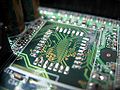
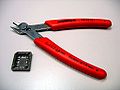
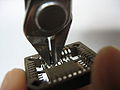
Desolder or cut away the ROM chip
-
...
-
...
-
-
...
-
-


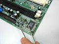
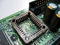
Clean the pads on the board


Prepare the PLCC socket
-
...
-
...
-
...
-


Solder the socket onto the board
-
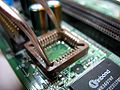
-
...


Resources
- HOWO: replace a PLCC chip with a socket "ghetto style" (Tutorial for doing this without desoldering station by cutting the chip)
| I, the copyright holder of this work, hereby release it into the public domain. This applies worldwide.
In case this is not legally possible: |