Board:lenovo/x201: Difference between revisions
No edit summary |
PaulePanter (talk | contribs) m (Convert URL to HTTPS) |
||
| (76 intermediate revisions by 8 users not shown) | |||
| Line 1: | Line 1: | ||
Thanks for your interest in the Lenovo X201 port of Coreboot. | |||
== Status == | == Status == | ||
Issues | === Issues === | ||
* Sometimes Gnome starts to think that battery is 10 time larger than real. Information from sysfs remains correct. Doesn't appear in newer gnome | |||
* Yellow USB port is not powered when computer is shut down or in S3. | |||
* Sometimes Gnome starts to think that battery is 10 time larger than real | * Most times after suspend an EC IRQ hangs in the queue and all functions keys stopped working until cold boot. | ||
Information from sysfs remains correct. | * '''Commit 456f495d broke USB and PCI-E''' (unable to boot from live ISO on USB), a hard reset to commit a3e41c08 fixed the boot issue, however the '''following issues occurred/persisted''': | ||
* | ** The X201 immediately powers off after resuming from suspend, sometimes resulting in a completely lost session. This is due to a race condition; see [http://review.coreboot.org/#/c/10352/ http://review.coreboot.org/#/c/10352/]. | ||
=== Tested === | |||
Tested | |||
* RAM module combinations of 4G+4G, 4G, 2G+2G,4G+2G, 2G | * RAM module combinations of 4G+4G, 4G, 2G+2G,4G+2G, 2G | ||
* USB | * Suspend to RAM (S3) '''(see issue mentioned above)''' | ||
* USB '''(see issues mentioned above)''' | |||
* Video (both internal and VGA) | * Video (both internal and VGA) | ||
* | * ExpressCard slot (including hotplug) | ||
* Sound | * Sound | ||
* LAN | * LAN | ||
* mini-PCIe slots (both wlan and wwan) | * mini-PCIe slots (both wlan and wwan) | ||
* Linux (through GRUB-as-payload) | * Linux (through GRUB-as-payload & SeaBIOS-as-payload) | ||
* Windows (through GRUB-as-payload loading SeaBIOS image from disk) | * Windows (through GRUB-as-payload loading SeaBIOS image from disk; you have to use extracted VGA blob, dumped from memory isn't good enough) | ||
* SD card slot | * SD card slot | ||
* Thermal management | * Thermal management | ||
Not tested | * Fingerprint reader | ||
* Webcam | |||
* Bluetooth | |||
* Digitizer on X201t variant. | |||
=== Not tested === | |||
* Modem | * Modem | ||
== | == Proprietary component status == | ||
* CPU Microcode | * CPU Microcode | ||
* VGA | * VGA Option ROM (optional): you need it if you want graphics in SeaBIOS but most payloads (e.g. GRUB2) work just fine without it (text mode or corebootfb mode) | ||
* | * [[Intel_Management_Engine|Intel Management Engine (ME) firmware]] => you do not have to touch it (just leave it where it is) | ||
* | * Embedded Controller (EC) => you do not have to touch it (just leave it where it is) | ||
== Code == | == Code == | ||
{{MergedIntoMaster|review_url=https://review.coreboot.org/#/c/4514/}} | |||
== Flashing == | |||
== | === Background info: flash layout === | ||
The flash memory in the X201 is divided into roughly 4 parts, readable and writable thus: | |||
Descriptor | {| class="wikitable" | ||
Rewriteable | !rowspan="2"|Part | ||
!rowspan="2"|Size | |||
!colspan="2"|With Flashrom on<br />the running system | |||
!colspan="2"|With Flashrom via<br />an external programmer | |||
|- | |||
! Readable | |||
! Writable | |||
! Readable | |||
! Writable | |||
|- | |||
| Descriptor | |||
| 12K | |||
| style="background-color: lime;" | Yes | |||
| style="background-color: red;" | No | |||
| style="background-color: lime;" | Yes | |||
| style="background-color: lime;" | Yes | |||
|- | |||
| [[Intel Management Engine|Intel Management Engine (ME) firmware]] | |||
| 5M minus 12K | |||
| style="background-color: red;" | No | |||
| style="background-color: red;" | No | |||
| style="background-color: lime;" | Yes | |||
| style="background-color: lime;" | Yes | |||
|- | |||
| Rewriteable flash | |||
| 3M minus 96K | |||
| style="background-color: lime;" | Yes | |||
| style="background-color: lime;" | Yes | |||
| style="background-color: lime;" | Yes | |||
| style="background-color: lime;" | Yes | |||
|- | |||
| Locked bootblock | |||
| 96K | |||
| style="background-color: lime;" | Yes | |||
| style="background-color: red;" | No | |||
| style="background-color: lime;" | Yes | |||
| style="background-color: lime;" | Yes | |||
|} | |||
To install coreboot onto the X201, we need to preserve the descriptor and the ME firmware, and to overwrite the rewriteable region and the bootblock. There are two ways to achieve this: | |||
rewriteable region and bootblock. | |||
* External flasher. | * External flasher. | ||
* Unlock bootblock | * Unlock bootblock. | ||
=== Method 1: external flasher === | |||
In addition to your X201, you will need an [https://www.flashrom.org/Supported_programmers external SPI flasher supported by Flashrom], connected to a PC capable of running Flashrom. | |||
==== Read the flash chip contents ==== | |||
Turn off your X201. | |||
Remove the following: | |||
* battery; | |||
* keyboard; | |||
* palmrest. | |||
Locate the SPI chip. It should be beneath a protective plastic sheet, under where the keyboard was, at roughly the location where the trackpoint was. Next to it, you should see the label "SPI1" silk-screened in white on the motherboard. | |||
{| | |||
|[[File:Lenovo-x201-bios-location-arrow.png |200px|thumb|center|Found it!]] | |||
|[[File:X201_flash_location.png |200px|thumb|center|Under the keyboard]] | |||
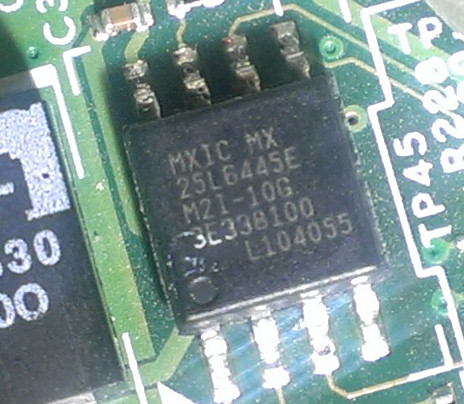
|[[File:Spi-soic8-25L6445E.png|200px|thumb|center|The SPI chip]] | |||
|} | |||
Connect your external SPI flasher to the SPI chip, ideally using a [https://www.flashrom.org/ISP SOIC-8 clip]. | |||
The pinout is as follows. (The colors in parentheses are those used by the [https://www.flashrom.org/Bus_Pirate Bus Pirate] breakout cable; your programmer may use leads with different colors. "N/C" means "not connected": these pins should not be connected to your programmer.) The top surface of the chip should have a small dimple or a dot of paint next to pin 1. | |||
^ Towards LCD display (i.e. away from you) | |||
| | |||
(red) (violet) (gray) | |||
3.3V N/C CLK MOSI | |||
_|_______|_______|_______|_ | |||
| | | |||
| 8 7 6 5 | | |||
| | | |||
| | | |||
| 1 2 3 4 | | |||
|___________________________| | |||
| | | | | |||
CS MISO N/C GND | |||
(white) (black) (brown) | |||
| | |||
v Towards front edge of laptop base (i.e. towards you) | |||
Not all external programmers supply enough current to enable reliable reads from and writes to the flash chip. If yours does not (as is the case with the Bus Pirate and the BeagleBone Black), then you may have to use a more powerful regulated power supply to feed the chip's 3.3V pin. '''Make sure not to exceed 3.3V.''' | |||
Read the flash chip's contents at least twice, using Flashrom. Compare the files to be sure they are identical. | |||
flashrom -p <yourprogrammer> -r flash.bin | |||
flashrom -p <yourprogrammer> -r flash2.bin | |||
diff flash.bin flash2.bin | |||
If you have trouble reading the chip successfully, check for an eliminate these common problems: | |||
*insufficient power supply; | |||
*bad contacts; | |||
*excessively long wires (even 10cm may be too long); | |||
*incorrect connections. | |||
For additional troubleshooting, see: [http://flashrom.org/ISP In-System Programming]. | |||
Once you have a good copy of the flash chip's contents, save a copy of the file to external media as a backup. | |||
==== Neutralize the Intel Management Engine (optional) ==== | |||
As of March 2017, Coreboot builds for the X201 are [https://github.com/corna/me_cleaner/issues/3 thought to be incompatible] with neutralized MEs: MEs neutralized with <code>me_cleaner</code> seem to work fine with the stock BIOS, but not with Coreboot. Making Coreboot compatible with neutralized MEs is a [https://www.coreboot.org/pipermail/coreboot/2017-March/083798.html work in progress]. | |||
If you wish to attempt to neutralize your X201's ME anyway, see the instructions [https://hardenedlinux.github.io/firmware/2016/11/17/neutralize_ME_firmware_on_sandybridge_and_ivybridge.html#05-neutralize-the-me here]. | |||
If you have attempted the neutralization, please report the success or failure of the attempt [https://github.com/corna/me_cleaner/issues/3 here], to help the Coreboot and <code>me_cleaner</code> developers to improve their efforts. | |||
3 | |||
==== Extract descriptor and Management Engine regions ==== | |||
dd if=flash.bin of=coreboot/3rdparty/blobs/mainboard/lenovo/x201/descriptor.bin \ | |||
dd if=flash.bin of=coreboot/3rdparty/mainboard/lenovo/x201/descriptor.bin \ | |||
count=12288 bs=1M iflag=count_bytes | count=12288 bs=1M iflag=count_bytes | ||
dd if=flash.bin of=coreboot/3rdparty/mainboard/lenovo/x201/me.bin \ | dd if=flash.bin of=coreboot/3rdparty/blobs/mainboard/lenovo/x201/me.bin \ | ||
skip=12288 count=5230592 bs=1M iflag=count_bytes | skip=12288 count=5230592 bs=1M iflag=count_bytes,skip_bytes | ||
==== Compile Coreboot ==== | |||
When compiling Coreboot, remember to enable <code>HAVE_IFD</code> and <code>HAVE_ME_BIN</code>, in order to incorporate, into the resulting build, the descriptor and ME firmware that you extracted earlier. The easiest way to do this is via <code>make nconfig</code> or <code>make menuconfig</code>: the relevant options are in the "Chipset" menu. | |||
The result will typically be a file called in the <code>build</code> directory called <code>coreboot.rom</code>. | |||
==== Flash Coreboot to the chip ==== | |||
Flash the resulting <code>build/coreboot.rom</code> to the chip, using Flashrom. | |||
=== Method 2: unlocking the bootblock === | |||
No-one has so far published any success with this method. In theory, however, it is possible. | |||
The locking mechanism is in the bootblock itself. The original firmware has a way to update it as follows. | |||
* Flash an update to the rewriteable region, containing a compressed copy of the new bootblock. | |||
* On next boot, the bootblock parses the rewritable region and sees that compressed copy. | |||
* That copy is uncompressed and flashed. | |||
A way to unlock the bootblock would be to modify a firmware update to have a copy of the bootblock without protection. For this you would need to compress the modified block to fit into original space. The compression used is Lempel-Ziv- Huffman variant. [[User:Phcoder|Phcoder]] has written a compressor for it, but stated that it was not performant enough. | |||
=== Appendix 1: how identify the regions on the chip === | |||
[root@x201 ~]# flashrom -r bios.bin -pinternal:laptop=force_I_want_a_brick | [root@x201 ~]# flashrom -r bios.bin -pinternal:laptop=force_I_want_a_brick | ||
flashrom v0.9.6.1-r1563 on Linux 3.10-1-grml-amd64 (x86_64) | flashrom v0.9.6.1-r1563 on Linux 3.10-1-grml-amd64 (x86_64) | ||
| Line 118: | Line 218: | ||
'''But as in this case, flashrom might misidentify the chip''', this output is from [[Media:Spi-soic8-25L6445E.png|this MX25L6445E]] | '''But as in this case, flashrom might misidentify the chip''', this output is from [[Media:Spi-soic8-25L6445E.png|this MX25L6445E]] | ||
visually verify your chip's part number and find an [http://www.macronix.com/QuickPlace/hq/PageLibrary4825740B00298A3B.nsf/h_Index/3F21BAC2E121E17848257639003A3146/$File/MX25L6445E,%203V,%2064Mb,%20v1.8.pdf appropriate datasheet ] | visually verify your chip's part number and find an [http://www.macronix.com/QuickPlace/hq/PageLibrary4825740B00298A3B.nsf/h_Index/3F21BAC2E121E17848257639003A3146/$File/MX25L6445E,%203V,%2064Mb,%20v1.8.pdf appropriate datasheet] | ||
=>verify that its voltage matches with the programmer voltage... | =>verify that its voltage matches with the programmer voltage... | ||
* | * Use flashrom layouts: | ||
-l, --layout <file> | -l, --layout <file> | ||
X201 Layout | |||
000000000:00000fff fd | |||
000001000:00002fff gbe | |||
000003000:004fffff me | |||
000500000:007fffff bios | |||
=== Appendix 2: how to flash specific regions of the chip === | |||
To flash only the bios partition (coreboot + payload) do: | |||
flashrom -l <layout> -i bios -w coreboot.rom | |||
Latest revision as of 13:01, 16 May 2018
Thanks for your interest in the Lenovo X201 port of Coreboot.
Status
Issues
- Sometimes Gnome starts to think that battery is 10 time larger than real. Information from sysfs remains correct. Doesn't appear in newer gnome
- Yellow USB port is not powered when computer is shut down or in S3.
- Most times after suspend an EC IRQ hangs in the queue and all functions keys stopped working until cold boot.
- Commit 456f495d broke USB and PCI-E (unable to boot from live ISO on USB), a hard reset to commit a3e41c08 fixed the boot issue, however the following issues occurred/persisted:
- The X201 immediately powers off after resuming from suspend, sometimes resulting in a completely lost session. This is due to a race condition; see http://review.coreboot.org/#/c/10352/.
Tested
- RAM module combinations of 4G+4G, 4G, 2G+2G,4G+2G, 2G
- Suspend to RAM (S3) (see issue mentioned above)
- USB (see issues mentioned above)
- Video (both internal and VGA)
- ExpressCard slot (including hotplug)
- Sound
- LAN
- mini-PCIe slots (both wlan and wwan)
- Linux (through GRUB-as-payload & SeaBIOS-as-payload)
- Windows (through GRUB-as-payload loading SeaBIOS image from disk; you have to use extracted VGA blob, dumped from memory isn't good enough)
- SD card slot
- Thermal management
- Fingerprint reader
- Webcam
- Bluetooth
- Digitizer on X201t variant.
Not tested
- Modem
Proprietary component status
- CPU Microcode
- VGA Option ROM (optional): you need it if you want graphics in SeaBIOS but most payloads (e.g. GRUB2) work just fine without it (text mode or corebootfb mode)
- Intel Management Engine (ME) firmware => you do not have to touch it (just leave it where it is)
- Embedded Controller (EC) => you do not have to touch it (just leave it where it is)
Code
{{ #if: https://review.coreboot.org/#/c/4514/ | * The code has been merged into coreboot master: | * The code has been merged into coreboot master:}}
$ git clone https://review.coreboot.org/coreboot.git
Flashing
Background info: flash layout
The flash memory in the X201 is divided into roughly 4 parts, readable and writable thus:
| Part | Size | With Flashrom on the running system |
With Flashrom via an external programmer | ||
|---|---|---|---|---|---|
| Readable | Writable | Readable | Writable | ||
| Descriptor | 12K | Yes | No | Yes | Yes |
| Intel Management Engine (ME) firmware | 5M minus 12K | No | No | Yes | Yes |
| Rewriteable flash | 3M minus 96K | Yes | Yes | Yes | Yes |
| Locked bootblock | 96K | Yes | No | Yes | Yes |
To install coreboot onto the X201, we need to preserve the descriptor and the ME firmware, and to overwrite the rewriteable region and the bootblock. There are two ways to achieve this:
- External flasher.
- Unlock bootblock.
Method 1: external flasher
In addition to your X201, you will need an external SPI flasher supported by Flashrom, connected to a PC capable of running Flashrom.
Read the flash chip contents
Turn off your X201.
Remove the following:
- battery;
- keyboard;
- palmrest.
Locate the SPI chip. It should be beneath a protective plastic sheet, under where the keyboard was, at roughly the location where the trackpoint was. Next to it, you should see the label "SPI1" silk-screened in white on the motherboard.
 |
 |
Connect your external SPI flasher to the SPI chip, ideally using a SOIC-8 clip.
The pinout is as follows. (The colors in parentheses are those used by the Bus Pirate breakout cable; your programmer may use leads with different colors. "N/C" means "not connected": these pins should not be connected to your programmer.) The top surface of the chip should have a small dimple or a dot of paint next to pin 1.
^ Towards LCD display (i.e. away from you)
|

   (red)        (violet) (gray)
   3.3V    N/C     CLK    MOSI
   _|_______|_______|_______|_
  |                           |
  | 8       7       6       5 |
  |                           |
  |                           |
  | 1       2       3       4 |
  |___________________________|
    |       |       |       |
   CS      MISO    N/C     GND
  (white) (black)        (brown)

|
v Towards front edge of laptop base (i.e. towards you)
Not all external programmers supply enough current to enable reliable reads from and writes to the flash chip. If yours does not (as is the case with the Bus Pirate and the BeagleBone Black), then you may have to use a more powerful regulated power supply to feed the chip's 3.3V pin. Make sure not to exceed 3.3V.
Read the flash chip's contents at least twice, using Flashrom. Compare the files to be sure they are identical.
flashrom -p <yourprogrammer> -r flash.bin
flashrom -p <yourprogrammer> -r flash2.bin
diff flash.bin flash2.bin
If you have trouble reading the chip successfully, check for an eliminate these common problems:
- insufficient power supply;
- bad contacts;
- excessively long wires (even 10cm may be too long);
- incorrect connections.
For additional troubleshooting, see: In-System Programming.
Once you have a good copy of the flash chip's contents, save a copy of the file to external media as a backup.
Neutralize the Intel Management Engine (optional)
As of March 2017, Coreboot builds for the X201 are thought to be incompatible with neutralized MEs: MEs neutralized with me_cleaner seem to work fine with the stock BIOS, but not with Coreboot. Making Coreboot compatible with neutralized MEs is a work in progress.
If you wish to attempt to neutralize your X201's ME anyway, see the instructions here.
If you have attempted the neutralization, please report the success or failure of the attempt here, to help the Coreboot and me_cleaner developers to improve their efforts.
Extract descriptor and Management Engine regions
 dd if=flash.bin of=coreboot/3rdparty/blobs/mainboard/lenovo/x201/descriptor.bin \
   count=12288 bs=1M iflag=count_bytes
 dd if=flash.bin of=coreboot/3rdparty/blobs/mainboard/lenovo/x201/me.bin \
   skip=12288 count=5230592 bs=1M iflag=count_bytes,skip_bytes
Compile Coreboot
When compiling Coreboot, remember to enable HAVE_IFD and HAVE_ME_BIN, in order to incorporate, into the resulting build, the descriptor and ME firmware that you extracted earlier. The easiest way to do this is via make nconfig or make menuconfig: the relevant options are in the "Chipset" menu.
The result will typically be a file called in the build directory called coreboot.rom.
Flash Coreboot to the chip
Flash the resulting build/coreboot.rom to the chip, using Flashrom.
Method 2: unlocking the bootblock
No-one has so far published any success with this method. In theory, however, it is possible.
The locking mechanism is in the bootblock itself. The original firmware has a way to update it as follows.
- Flash an update to the rewriteable region, containing a compressed copy of the new bootblock.
- On next boot, the bootblock parses the rewritable region and sees that compressed copy.
- That copy is uncompressed and flashed.
A way to unlock the bootblock would be to modify a firmware update to have a copy of the bootblock without protection. For this you would need to compress the modified block to fit into original space. The compression used is Lempel-Ziv- Huffman variant. Phcoder has written a compressor for it, but stated that it was not performant enough.
Appendix 1: how identify the regions on the chip
[root@x201 ~]# flashrom -r bios.bin -pinternal:laptop=force_I_want_a_brick
flashrom v0.9.6.1-r1563 on Linux 3.10-1-grml-amd64 (x86_64)
flashrom is free software, get the source code at http://www.flashrom.org

Calibrating delay loop... OK.
Found chipset "Intel QM57". Enabling flash write... WARNING: SPI Configuration Lockdown activated.
FREG0: WARNING: Flash Descriptor region (0x00000000-0x00000fff) is read-only.
FREG2: WARNING: Management Engine region (0x00003000-0x004fffff) is locked.
PR0: WARNING: 0x007d0000-0x01ffffff is read-only.
Please send a verbose log to flashrom@flashrom.org if this board is not listed on
http://flashrom.org/Supported_hardware#Supported_mainboards yet.
Writes have been disabled. You can enforce write support with the
ich_spi_force programmer option, but it will most likely harm your hardware!
If you force flashrom you will get no support if something breaks.
OK.
Found Macronix flash chip "MX25L6405" (8192 kB, SPI) at physical address 0xff800000.
Reading flash... FAILED.
it will print the ME regions:
FREG2: WARNING: Management Engine region (0x00003000-0x004fffff) is locked.
it will also print the chip:
Found Macronix flash chip "MX25L6405" (8192 kB, SPI) at physical address 0xff800000.
But as in this case, flashrom might misidentify the chip, this output is from this MX25L6445E
visually verify your chip's part number and find an appropriate datasheet
=>verify that its voltage matches with the programmer voltage...
- Use flashrom layouts:
-l, --layout <file>
X201 Layout
000000000:00000fff fd
000001000:00002fff gbe
000003000:004fffff me
000500000:007fffff bios
Appendix 2: how to flash specific regions of the chip
To flash only the bios partition (coreboot + payload) do:
flashrom -l <layout> -i bios -w coreboot.rom